Multicell Lithium Battery Charging & Balancing circuit
You probably know that charging lithium batteries isn’t particularly easy. But if you have just a single cell, you can get an IC to do this for you – the most popular being probably the TP4056 or the MCP73831 (you can get both of them from Ebay). But if you want to have a battery pack with multiple cells in series, well, then it gets really complicated. Two cells are never the same, so you need to balance individual cells during charging and also watch out for undervoltage/overvoltage on each cell while in use.
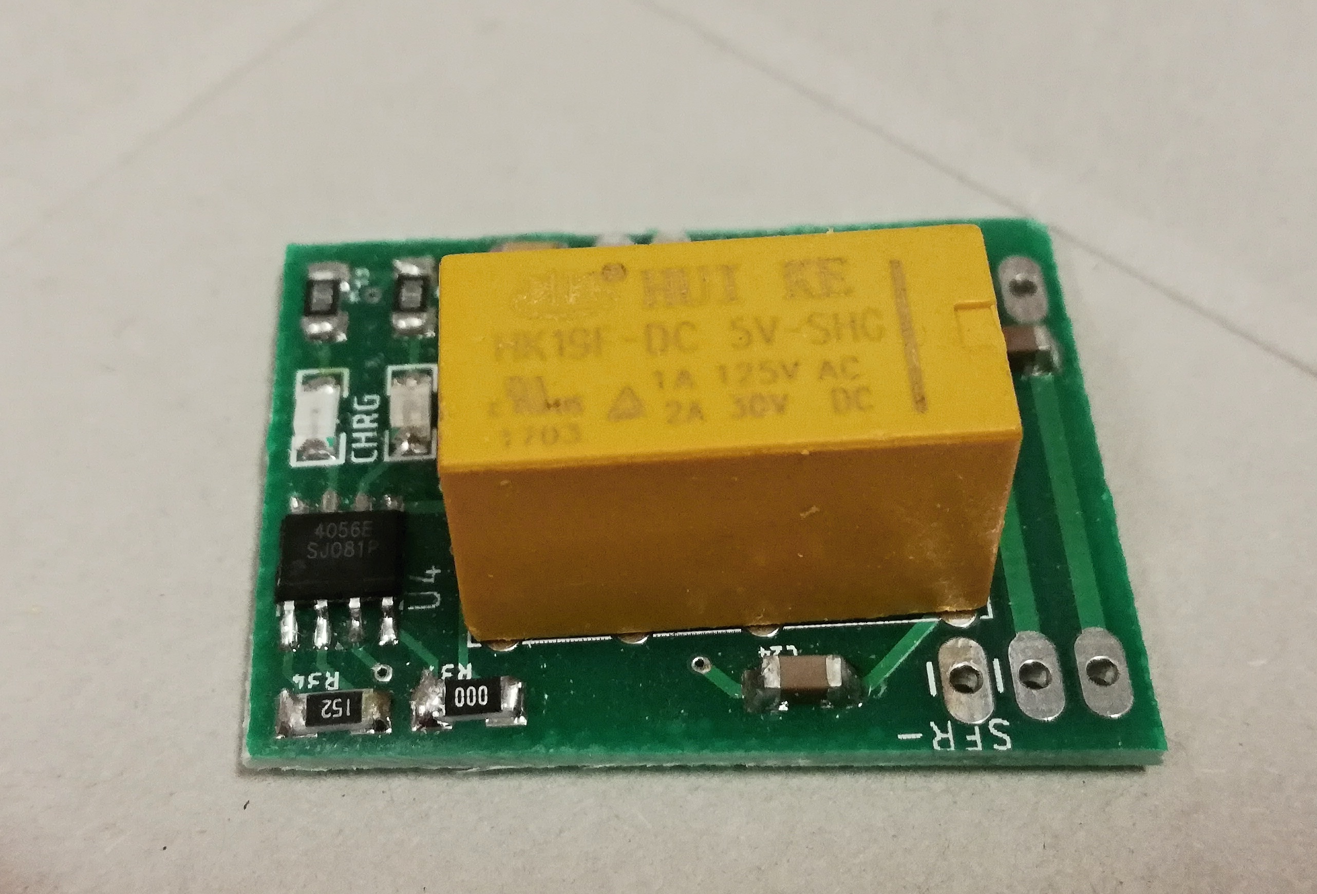
Unfortunately, there isn’t a cheap IC that would charge & protect & balance multicell packs. But recently, I made a simple board with easy-to-get components, which does all three of these things. The idea is simple – each cell has its own charging TP4056, which is connected via a DPDT relay to the cell (and it’s protection circuit). When you disconnect the 5 V input, the relay switches to the NC position, disconnecting the charger and connecting all the cells in parallel.
The trick with Relays
So the trick is simple – by using relays, we are switching between series connection (when the voltage of the cells adds up, and every cell is individually protected) and connection to the charger, when we can charge all of the cells using a single 5 V power supply.

Advantages
- no need to balance the cells, since they are all charged to the same voltage
- each cell is protected against overvoltage, undervoltage, overcurrent and short-circuit
- theoretically unlimited amount of cells in series (but the charging time is increased with each series cell)
Disadvantages
- the cells are charged in parallel, meaning you need low voltage and high amperage for charging, which limits the amount of cells you can use
- each series cell can be charged at 1 amp maximum (unless you substitute your own charging IC)
- you cannot charge and use the pack at the same time
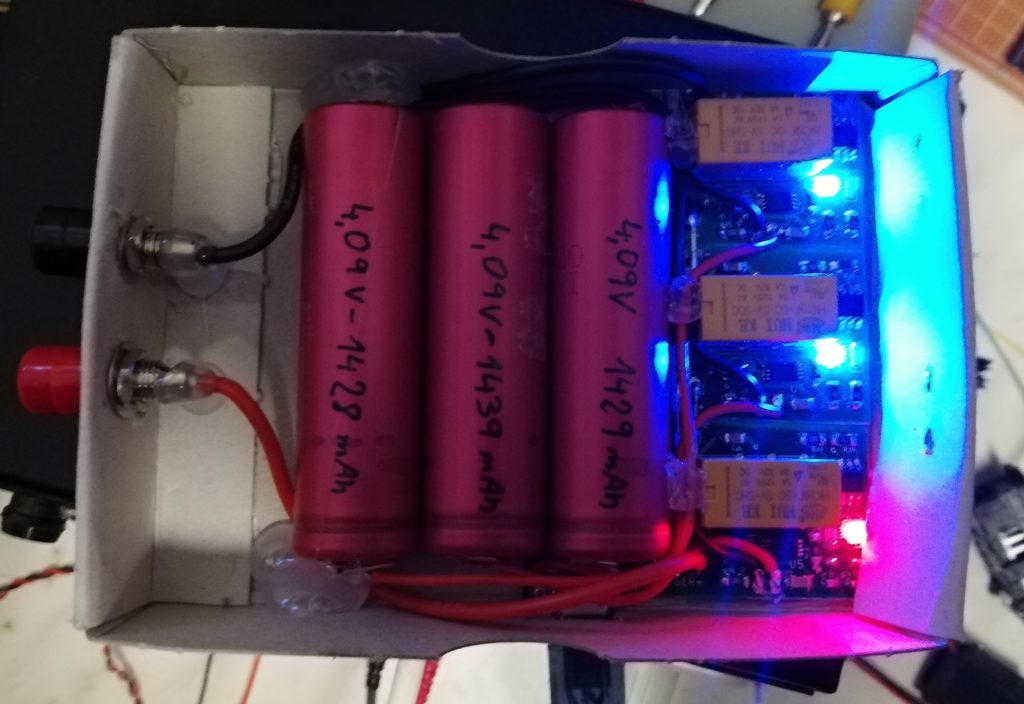
With these boards, I made a simple 3S1P pack (aka ~12 V) which I use in my lab as a low noise floating 12 V source:
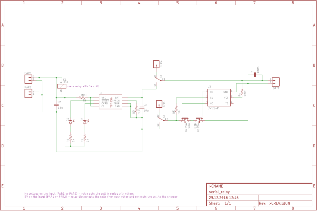
I do have a schematics and board layout in Eagle, but they have been done almost 2 years ago, so the board layout is pretty crappy and I advise you to rework it. I am not going to rework it, since I am currently working on a BMS using the ATmega88, which will (hopefully) provide the same functionality at fraction of size. But for some applications, this design might be useful. As always, all of my files are on my GitHub.
Very interesting, thank you Martin.
I very much look forward to seeing the BMS using the ATmega88 you have in the pipeline.
My charge application would be for 2x 18650 cells in-situ, capable of delivering power or of being charged as the circuit is being powered by externally input volts, allowing me to run the unit I have either by the batteries or on a lead without any drop-out as a changeover is made.
Any advice you could furnish would be really appreciated.
Fi
Hi,
it will take me some time to finish the ATmega88 battery controller, as I have a lot of other projects I am working on right now.
If you want to use two cells in series as a battery backup, maybe you do not need to charge them with balancing – just put protection on each cell and charge the whole pack with CC-CV supply (use cells from the same series) – it might work in the short term. Otherwise, you will probably need to wait for my project to be finished or find some other solution 🙂
regards, M.
Rather ingenious, thanks!
What I thought would be really nice was DC to DC converters with isolated outputs to charge individual lithium cells. If one had (eg) a 36 volt electric car with 12 cells in series (300 amp-hours BTW), 12 individual chargers each at 3.6 volts (adjust as desired) all connected to a single DC power source (solar panels) could charge the car without any danger of overcharging any one battery. I would think each charger would be bolted onto its battery via one (or both) of the posts.
To me that seems simpler than a charger that connects to all the cells and has to monitor each one, or putting individual shunts on each battery. (Any comments on that?) So far I haven’t seen anything that looks like it would work. (I suppose I could look up buck converter circuit diagrams with isolated outputs and make such chargers myself – ugh!)
Well, I think that on a large scale, this would be more than possible. But for my purposes (ie 3S1P battery), that would probably take up more space than the battery itself… (and also it would be pretty expensive).