Seven Segment Multifunction Display
Often, when I am prototyping something on a breadboard or elsewhere, I need to see voltage levels at multiple points of the circuit. Of course you can hook up multiple multimeters, but a) I don’t have that many multimeters and b) they are usually relatively big and take a lot of space on my small desk.
Furthermore, seven segment displays are nice and cheap and everything, but they require a lot of wires (12 for a four digit version, to be exact), which makes prototyping or just connecting them to anything a nightmare. For these two reasons, I decided to make a simple seven segment display board, which can either operate in ADC mode (measuring voltage), UART mode (displaying value from UART) or I2C mode (again, displaying characters). So, to summarize my goals:
- as small as possible, powered by two AAA batteries
- 2 ADC input ranges (0 – 6 V; 0 – 30 V)
- as cheap and simple to make as possible, so I can make a couple of these
- UART input and output with adjustable baud rate
- I2C input with configurable address
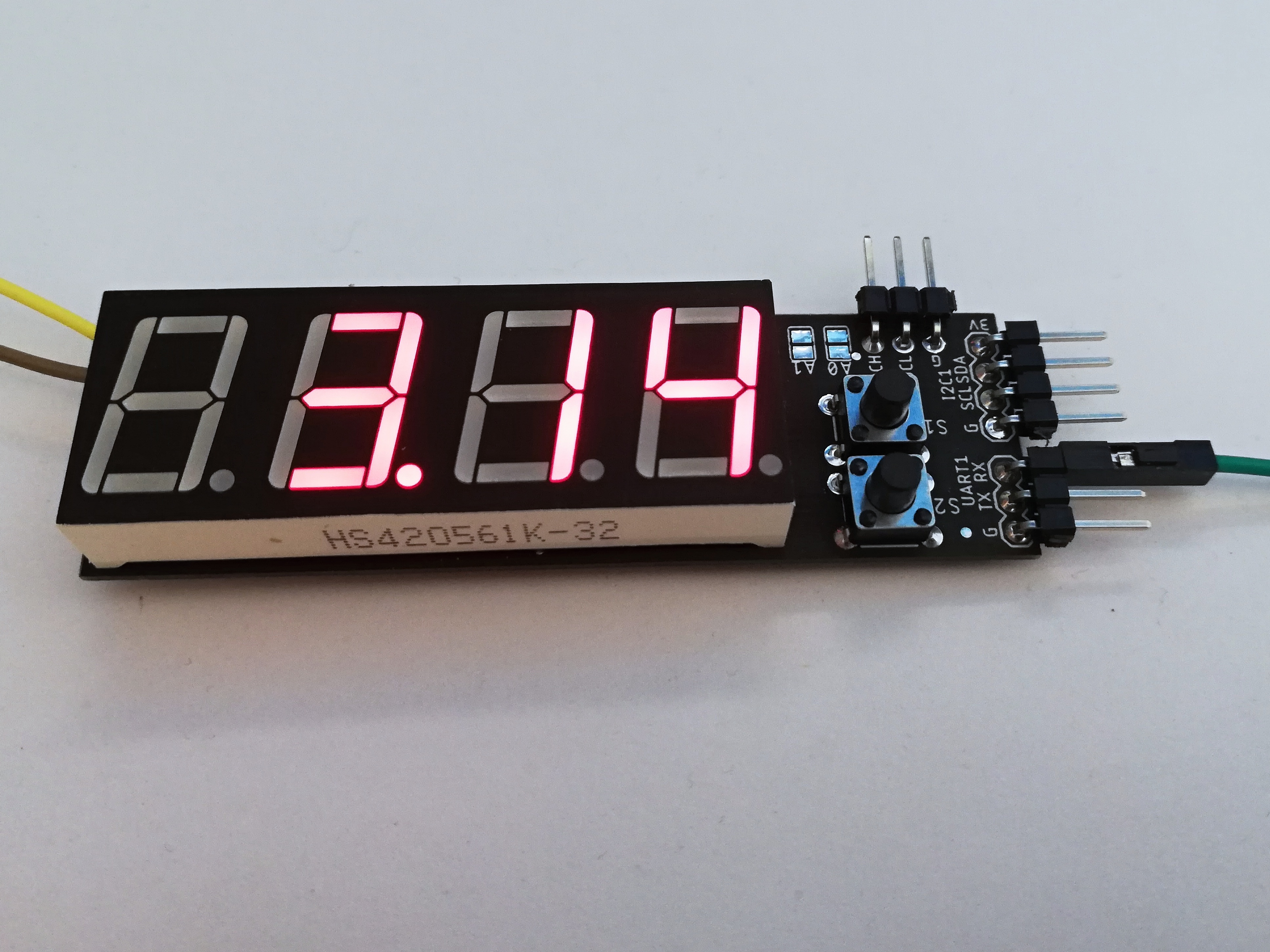
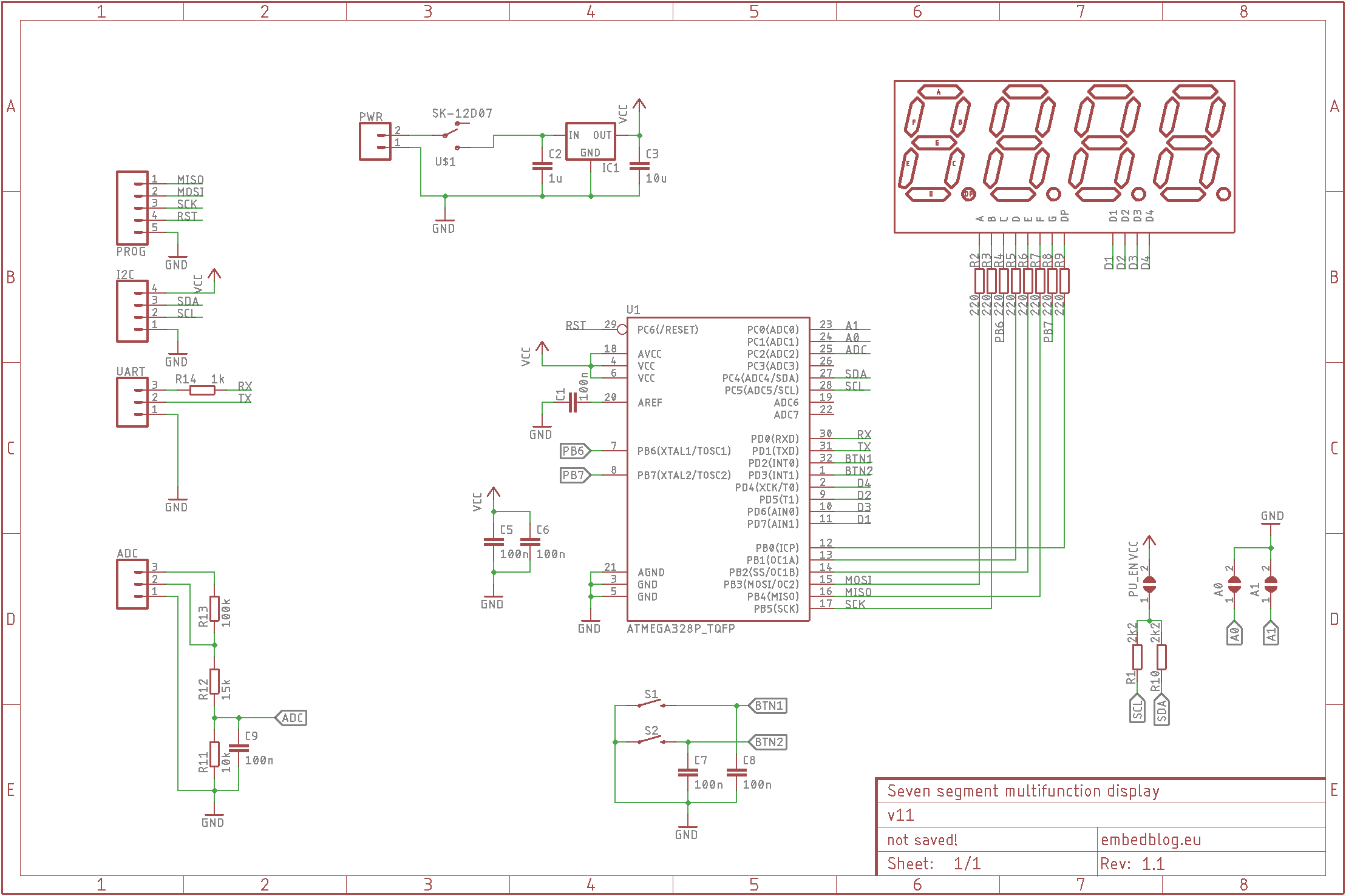
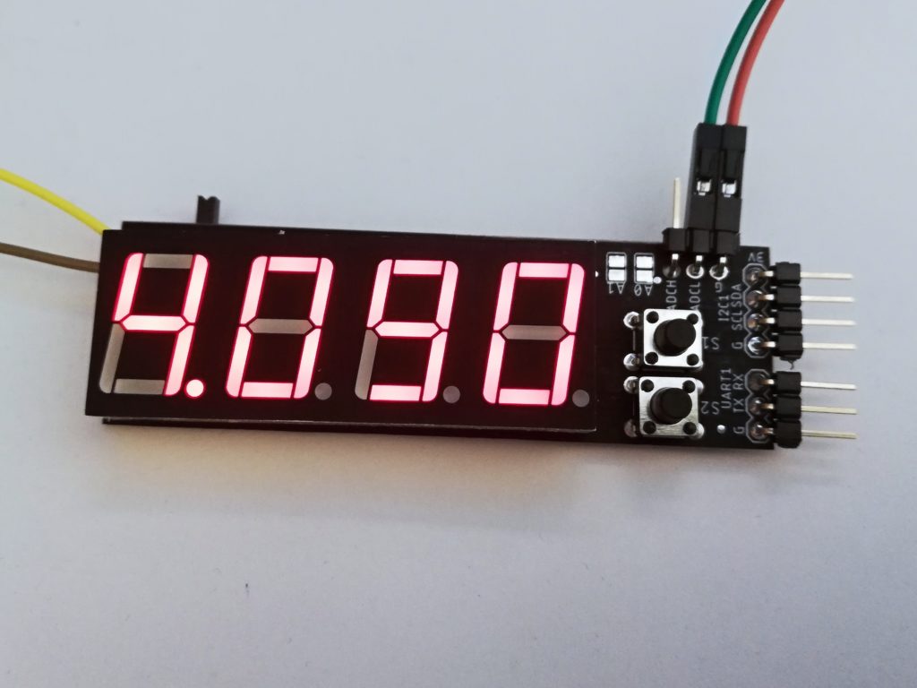
The design is not complicated – it’s just an ATmega88 (you can use any ATmega from the 48 to the 328), a 0.56″ common anode display, MCP1700-2.5 precision voltage regulator, two buttons and some other jellybean components. The only user control elements are two buttons: MODE (which is used to change mode – available modes are ADCL, ADCH, UART and I2C) and UTIL (whose function depends on the actual mode). There are also three solder jumpers – two set the I2C address and the last one enables integrated pullup resistors. Here’s the schematics:
ADC
The analog front end (AFE) has two inputs, called ADCL (with a range of 0 – 6 V) and ADCH (with a range of 0 – 30 V), which correspond each to a mode with the same name. To switch ranges, you need to press MODE until you get into the corresponding mode and you also need to physically move the cable to the corresponding pin. You can use the other button – UTIL – to freeze the display (similar to a HOLD function on a classical DMM).
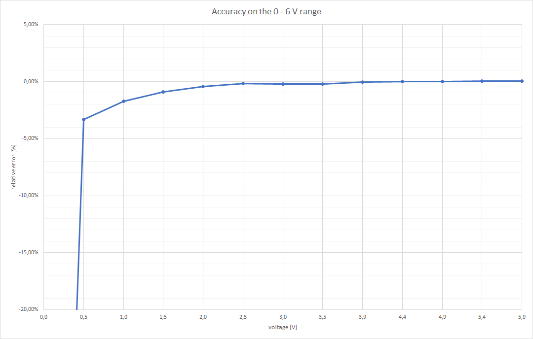
The input is not bipolar (meaning you cannot apply negative voltages to the input pin), but since the whole device is battery powered, you can easily just swap the polarity of the entire device. The AFE relies on the internal diodes of the ATmega to protect it from overvoltage or reverse polarity. Because the ADC works continuously and then averages the input (rather than taking just a single measurement when needed), it is relatively accurate – without calibration, the biggest error on the 6 V range was 17 mV! Here you can see the accuracy curve (measured with a Brymen 867s):
And here’s the 0 to 30 V range:
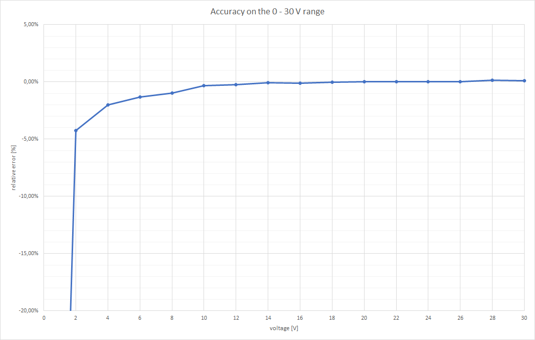
As you can see, in the 6 V range, the accuracy is better than 1 % with voltages higher than 1.5 volts. That’s pretty impressive, given that the whole think costs less than 4 dollars! With the 30 V range it is a similar story – with voltages higher than 6 V you can count on the sub 1 % accuracy.
UART
The display can be controlled via serial to display the message – it supports numbers, dash, dot, underscore and space. Simply sent four of these characters via UART in ASCII and it will display them. If you want to display less than four characters, simply send a line feed or a carriage return character. The baud rate is adjustable using the UTIL button – available values are 9.6, 19.2, 38.4, 57.6, 115.2 and 1000 kbaud. The input is 5 V tolerant.
I2C
The last option for displaying characters is to use I2C. This works really similarly to the UART mode with the same capabilities, except this way, you can connect multiple board to a single bus, thanks to the two address jumpers. The default address (no jumpers shorted) is 0b010100 and the jumpers change the last two LSBs (e. g. if you bridge jumper A0, the address will become 0b010101). However note that the I2C pins will not work with 5 V logic (they work with 3.3 V though). To interface it to a 5 V device, you need to build a level shifter, such as this one.
Conclusion
Except the fact that I managed to flip the silkscreen upside down, the result is OK – the analog accuracy is really good, but in future versions, I would like to change it in such a way that you do not need to swap the wire between ADCL and ADCH pins. The UART and I2C functionality works as expected.
As always, all of the source files are on GitHub.
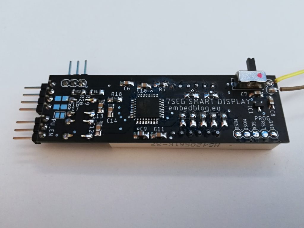
How do you solder these SMD components ?
All of the passive SMDs are 1206 footprint, so that’s not hard to solder by hand. What I sometimes do is populate 1206 footprints with 0805 parts, as that makes it really easy to solder. Otherwise, for some SMD soldering tricks, look it up on the Internet, there are tons of materials…