STM32 Open Source Multimeter
There is a new version. Read about it here!
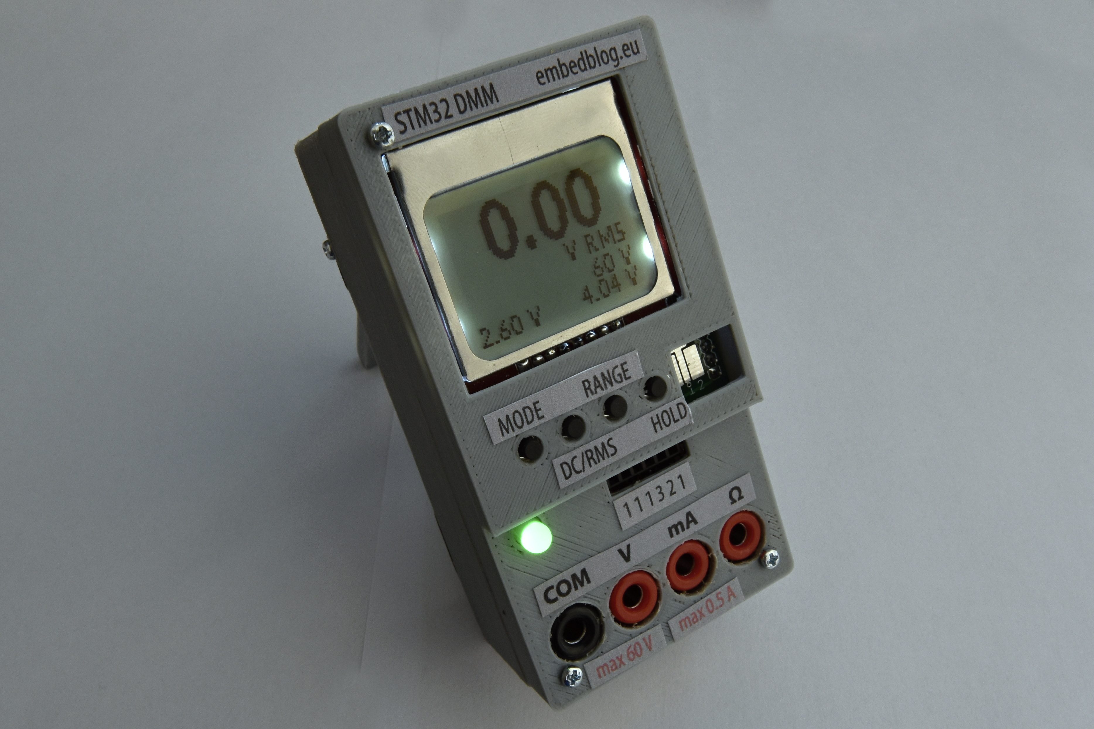
One of the most essential tools for anybody interested in electrical engineering is certainly a Digital Multi Meter (DMM). The problem is you really never have enough of these – there is always one more voltage or one more current that you need to measure when testing a circuit. So about a year ago I thought, why not try making one? And now, finally, I have a presentable result, which is by no means perfect, but I think it is a really interesting and usable device. So here’s a short video of what I have after three revisions and countless hours of programming and developing:

Why?
That’s a good question. If you look on Ebay, you’ll find hundreds of multimeters there, from cheap 7 USD no-name ones to a several hundred dollars Fluke ones. So if I want more multimeters, why not just buy more of those cheap ones?
Well, there are other reasons why I decided to make my own. First is of course curiosity – I wanted to see what I can achieve with a 32-bit processor, some programming and about 10 dollars worth of parts. Then there are features – those cheap multimeters almost never have digital data output for automated measurements, they don’t measure RMS, they cannot measure power (ie voltage and current at the same time), you need to turn a large dial to switch ranges and so on.
Disclaimer
This is meant mostly as an educational project. While it is totally usable (in fact, I have been using this as my “daily multimeter” for a while now), it is not meant to replace a commercially bought multimeter, more like complement it.
Also, because of safety, the maximal input voltage is ±60 V. Sure, you could just change the resistive divider so that it can accept even mains voltage, but don’t do that. There is very little in terms of safety isolation, that’s why I limited the input to such a low voltage – according to internationally recognized standards, voltages below 50 V AC and 120 V DC are still relatively safe to touch, so even if something goes wrong, you still should be fine. But anyways, I very rarely work with voltages above 60 V, so this is not really a limitation for me.
Features (rev. 1.2B)
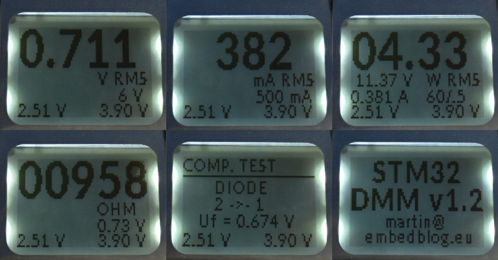
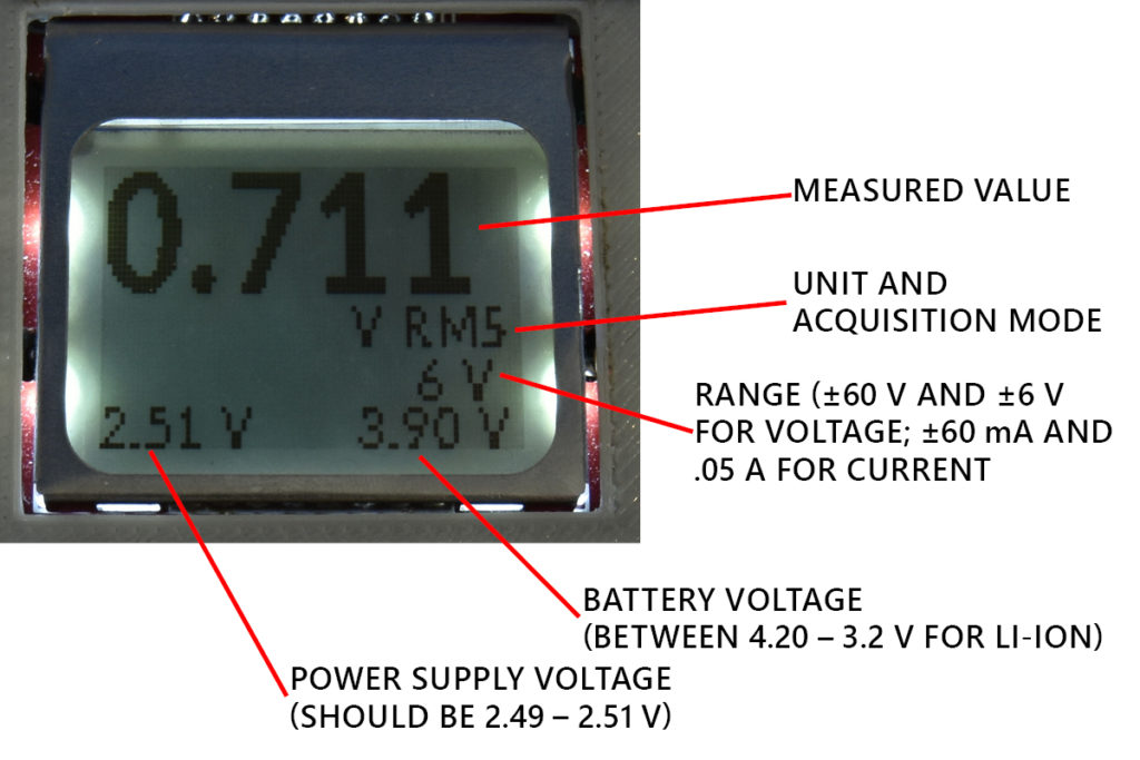
As I said, I am not aiming at fully replacing a commercially made multimeter – my goal is mostly having something small, cheap and accurate, capable of measuring voltage and current, because those things usually change in your circuit-under-test and you need to measure multiple of these at the same time. The meter features 6 “modes”, shown on the picture below:
Voltage & current
Voltage can be measured in two ranges: ±60 V and ±6 V. I choose these ranges because very often I work with circuits powered by 5 V, so the 6 V range is very handy. Current has two ranges as well, ±60 mA and ±500 mA.
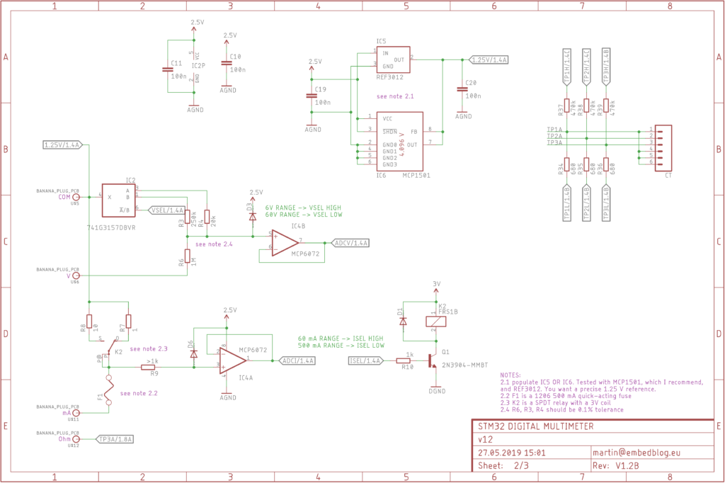
First design challenge was designing a bipolar input. Most of these “DIY hobby Arduino voltmeters” accept only positive voltages and blow up if you accidentally switch polarities, which is obviously something I did not want. Another approach (more professional) is to generate a negative rail and then use an opamp to offset the voltage. But again, generating a negative voltage rail requires additional parts and introduces a ton of noise. So I’ve designed an AFE (Analog Front End) which doesn’t require any negative voltage whatsoever and still supports bipolar input. The only downside is that the “ground” is offset by 1.25 V in this case, so we need to subtract that when we sample it with the ADC.

Another design challenge was that I wanted the range to be electrically selectable – so no hardware switches, like on these cheap multimeters. Electrically selectable range allows you to do autoranging, which is handy especially when controlling the multimeter from a PC. This is achieved using an 74-3157 analog switch for voltage and a relay for current, and I think this is another interesting part of this circuit.
Finally, after the signal is conditioned using the AFE, it is fed thru a buffer into the microcontroller’s ADC. Unfortunately, the ADC does not support differential input (which is a pity, we could really use it here), so it always takes two samples and subtracts them. The ADC is also 4x oversampled, resulting in a theoretical resolution of 14 bits. Finally, there are two acquisition modes – AVG and RMS.
AVG, which stands for average, as you’ve probably guessed, measures the DC or average voltage/current. So if you have a sinewave with 2 Vpp and 0 V offset, it will return 0. If you have the same sinewave, but with 1 V offset, it will return 1. So it’s basically what would be called “VDC” or “IDC” on your multimeter. This device also measures True RMS (effective value) – it takes about 30 000 samples every second and calculates the RMS value from that, according to a well known formula. So the first sinewave would return 0.7 volts, the second 1.7 volts. But it works on all kind of waveforms, it is by no means limited to sine. You can switch acquisition modes by pressing the RMS/DC button.
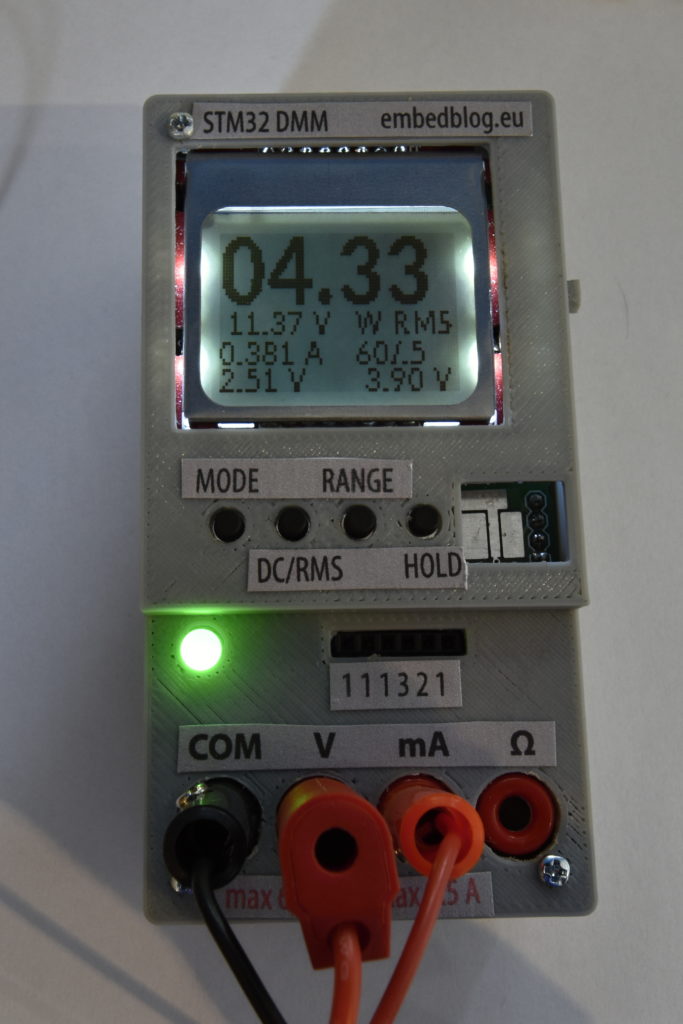
Power
Another feature I lack on most multimeters is the ability to measure voltage and current at the same time. So if you want to test, let’s say, effectiveness of a power supply, you need to use 4 multimeters at once. 4! Getting 4 multimeters is costly, it takes a ton of space on your desk and makes wiring a nightmare. And I am not even talking about the fact that you still need to multiply the corresponding voltages and currents to get power.
Implementing this was actually quite easy, you can see the screen below. Again, you can switch ranges (all 4 combinations possible), change acquisition mode (DC or RMS) or freeze the display using the hold button.
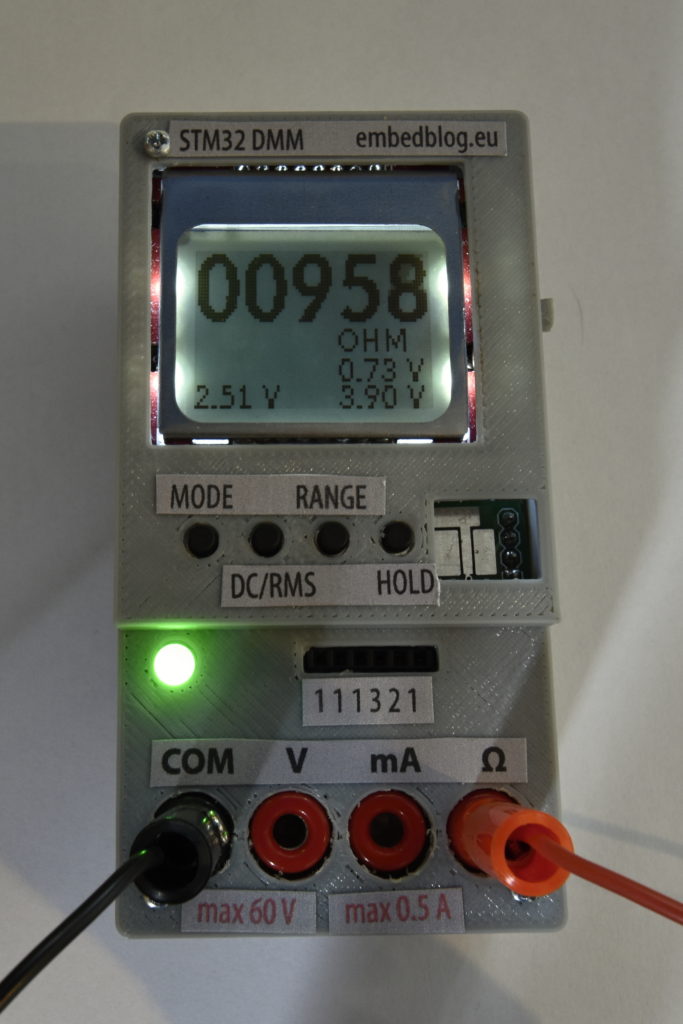
Continuity test
If I was to name three functions I use the most on a multimeter, it would be (in no particular order) voltage, current and continuity. So I implemented it as well – it shows the detected resistance and sounds a buzzer if it is below 50 Ω. Also the voltage drop across the device-under-test is shown, this is very useful for testing diodes.
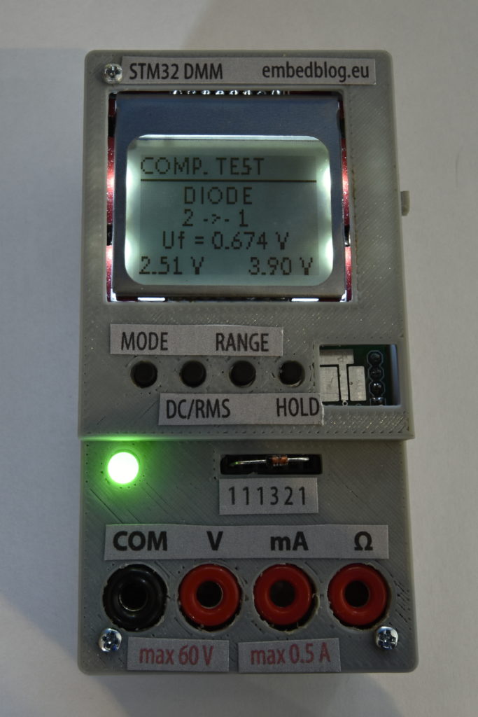
Component test
The last testing mode is a component test. As of now, it only supports resistors, capacitors and diodes, even though the hardware is compatible with the venerable “AVR component tester”. But as of now testing 3 pin semiconductors is not implemented, because I simply do not find it that useful. Also I attempted to make a SMD test pad (the hole right from the buttons), which works (and it is actually useful for testing like SMD capacitors, because they don’t have capacity ratings written on them), but the pad is too sunk into the enclosure.
Connectivity
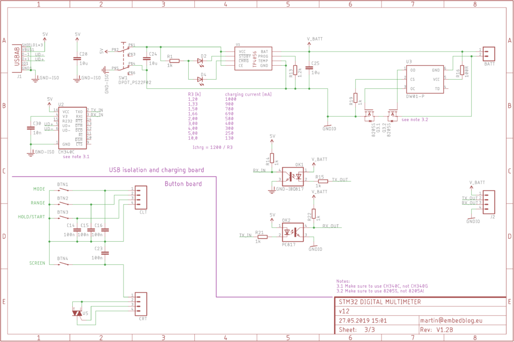
The multimeter features fully isolated USB port (acts as a serial emulator), which periodically sends data to the host PC. It can also receive data from the PC.
Then there is also an I2C port, which can be used for some additional modules (from the top of my head, some sort of EEPROM, radio/WiFi module for remote logging, external display like my 7 seg multifunction display) and also a SWD port for programming.
Accuracy
Now for the most important part – of course this whole thing would be useless, if it wasn’t accurate or reliable. When I made the first revision, I was blown by how accurate it actually was! Here a chart, showing the relative accuracy on the 6 V range:
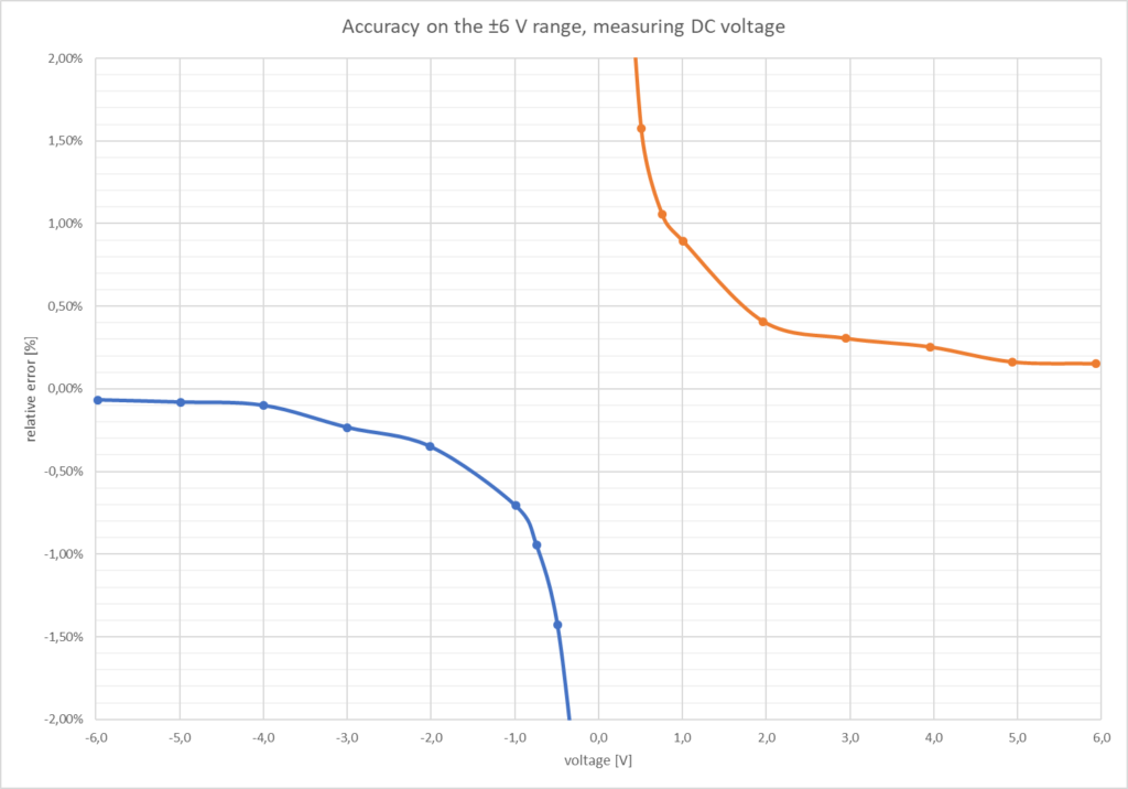
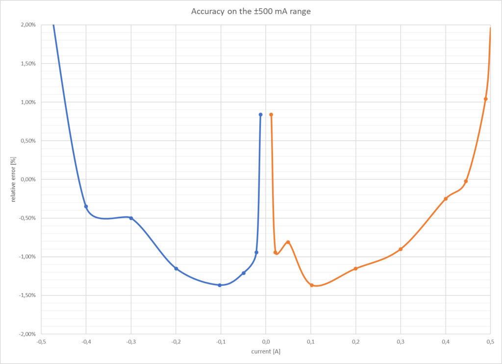
Of course this is for DC. This multimeter can also measure RMS of different waveforms, which can be seen for example in the video at the top of the page. Also here’s the accuracy for current measurement:

The accuracy for the remaining modes is OK, the component test can usually get within 5 % of the real value. Here the code could surely use some improvements.
Possible future upgrades
- data logging to SD card
- counting miliamphours and miliwatthours
- measuring phase angle (cos φ) and calculating apparent & reactive power
- 600 mV range & higher current range (coming in rev. 1.3, hopefully)
- polish the software to better display very small or very large values
- autoranging
- frequency counting
- calibration
- use a more powerful and precise STM32F3 series processor (those are nice, but not particularly easy to get)
Hardware
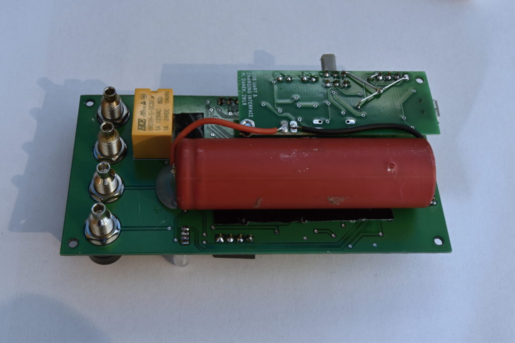
The meter itself consists of three PCBs – the main board, where all the processing and analog acquisition happens, the button board, which just extends buttons and the SMD test pad and the USB board, which deals with charging and protecting the battery and isolating the USB interface. There is a switch which connects power from USB to the charging circuit. When not switched, the circuit is totally isolated from the USB.
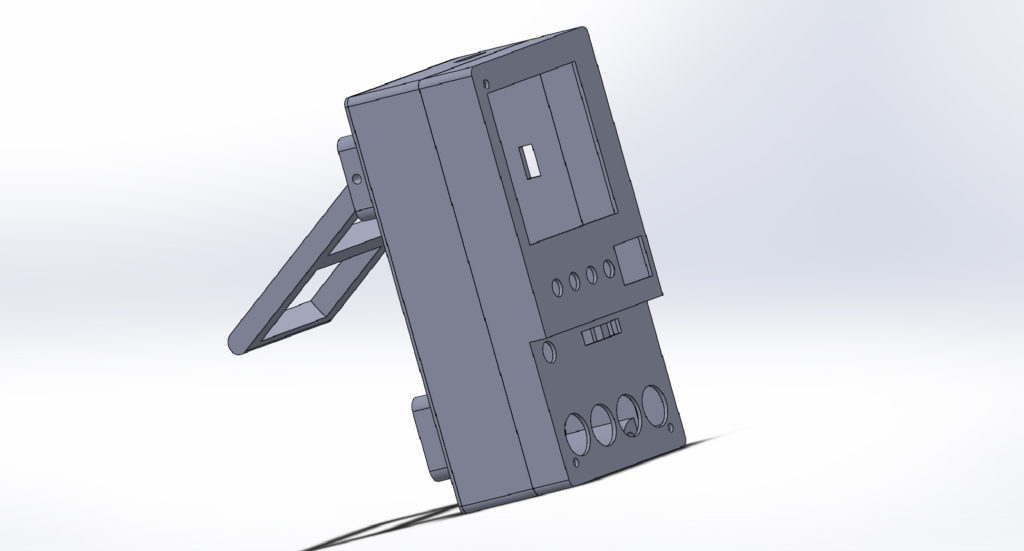
All of this is housed in a 3D printed case which I designed. Button names etc. are printed on self-adhesive paper and glued to the case. This looks ugly, but so far it is the easiest method of putting small print onto 3D printed objects. Everything is then screwed together using M2 screws and brass M2 threaded insert nuts. I also recommend that you stick rubber feet on the designated spots on the case, since 3D printed PLA has very little friction with hard surfaces and so the whole meter would tend to move around your table, if you for example pulled slightly on one of the leads.
Conclusion
I am very satisfied with the result – as I stated above, I’ve been using this device as a multimeter almost daily for the past month or so. There are still improvements which could be done and functions, which could be added (it is mostly a question of writing them just in software).
License: everything is licensed under CC BY-NC-SA 4.0 (Attribution-NonCommercial-ShareAlike 4.0 International)

WOW, This is a great writeup and a great project!
Thank you for sharing.
Hey. Nice project. I’m new to electronics and I wonder if you could help me understand the bipolar AFE? I’m confused about the connection of the 1.25v reference to the COM terminal. If we ignore the switch and assume it is hardwired for the 6v range, the idea is that the probes can be connected backwards and it would still read OK?
If I calculated correctly, then the ‘right’ way gives a voltage of 2.45v going into the OpAmp. I guess the diode is for over-voltage protection and the OpAmp input is limited to 2.5v?
However, I couldn’t figure out how it works if the probes were to be reversed and you have -6v going in. Can you explain? Thanks.
Hi,
you are right in your assumptions. So lets ignore the switch and lets say it’s in the 6 V range. Then we basically have a 1:4 resistive divider, but the bottom of the divider is not connected to ground – instead it is offset by 1.25 V. So if you plug in 5 V signal “the right way”, it will divide it to be 1 V + this 1.25 V offset = 2.25 V. So the ADC will read 2.25 V referenced to ground. But if you connect the probes backwards, you’ll have -5 V signal divided to -1 V. But this -1 V is now offset by 1.25 V, so the result is -1 + 1.25 = 0.25 V. So the ADC will read 0.25 V referenced to ground.
This is actually a neat trick – this way you can make any unipolar ADC bipolar! The only downsides are a) little more noise and b) if you connected this to you PC with non-isolated connection and then tried measuring an Arduino, which is also connected to the PC, you might burn something. That’s why this includes an isolated USB.
Thanks for taking the time to respond. I guess I’m now more confused. What do you do when it shows 0.25V? I initially thought that you would somehow set it up so that when you reverse the probes, you somehow end up with the same voltage going to the ADC so it doesn’t matter which way you put it, but from your explanation, you manage to get it into a ‘safe’ voltage range, but the voltage is completely different than if the probes were not reversed? Does the software somehow detect and correct this? Or is it just a protection circuit? Why not make the AFE give the same voltage when probes are reversed – wouldn’t this be better/easier? Thanks again! 🙂
So, the ADC basically subtracts the reference voltage (1.25 V) from every value. If the ADC measures 0.25 V, it subtracts 0.25 – 1.25 = -1. Then it is multiplied by the divider ratio – 5 in this case – and you arrive at the result, -5 V. So simply put, since the COM terminal is offset by 1.25 V, all voltages in the range <0; 1.25> V are in reality ‘negative’, and all voltages in the range <1.25; 2.5> are positive.
What you are saying is also possible – basically build a rectifier – but then how do you detect the true polarity? Also it is not that easy, you need to use an op-amp as an ideal diode.
However even my approach has disadvantages – especially the precision about 0 V isn’t great.
Thanks for your answer and patience. Since I’m pretty new to all this and trying to learn, I’m going to put a cold towel on my head and read what you wrote carefully to try to figure it all out! Thanks again! 🙂
OK. After a bit of a think I understand what you did. The thing I got wrong was I thought you were trying to map 0-6v into 0 – 2.5v and then map -6v-0v to the same 0-2.5v range. However, you are right to point out that while you can do this, you would need to detect the polarity another way. I guess this can be easily done using a comparator.
One advantage I see with using this alternative approach is that you would use the full 0-2.5v range for each ‘half’ of the input voltage range and so gain some resolution.
I saw an example here where they have this ‘symmetrical’ input: https://masteringelectronicsdesign.com/design-a-bipolar-to-unipolar-converter/
Thanks again for your feedback and the great project. It inspired me to try to make something similar (but simpler!).
Take a look at this STM32L152 based Digital Multimeter. I wonder how easy this would be to hack through the com port. Let me know your thoughts and please get in touch. https://youtu.be/xRkMdbNCBWo
Hmm interesting. Based on your review, it has a dedicated front end IC + a processor. These L152s have a UART bootloader, so this could come in handy. However, generally hacking a 200 USD+ multimeter might not be such a great idea, as not many people can afford it and also, what features would you like to add? At least to me, it seems relatively well programmed….
Hi ;
I`m trying to make a digital multimeter to measure true RMS of any priodic siganl , now my question is :
Is this DMM can measure and report True RMS of any proidic signal or NOT???
please contact me :
alibagherian192@yahoo.com
Hi,
as mentioned in the article, yes, it can measure RMS even of non-periodic signals. But the sample rate is 50 kSps, so the bandwidth will be like 10-20 kHz.
you know my UNI project is to build a DMM that can measure True RMS of priodic signals between 40Hz to 40KHz and with the high accuracy
now can I use this project or not ??
and other is can you explain more about the program?
I wanna to know more about how dose it work.
thanks a lot
As I said above, the RMS bandwidth is limited by the sample rate of the sigma-delta ADC. So you would need to use the built-in SAR ADC or use an external ADC.
I am not going to explain you the working of the whole program. Have a look at GitHub, go thru the code and ask exact questions.
Another question is Can I use STM32F103 header board for this project??
Again, if you are going to build this, you should be capable or reading datasheets. So find the datasheet for STM32F103 and the STM32F373, find the pinouts for TQFP48 package and compare them side by side. This should clearly anwer your qeustion.