STM32 Open Source multimeter – revision 1.3
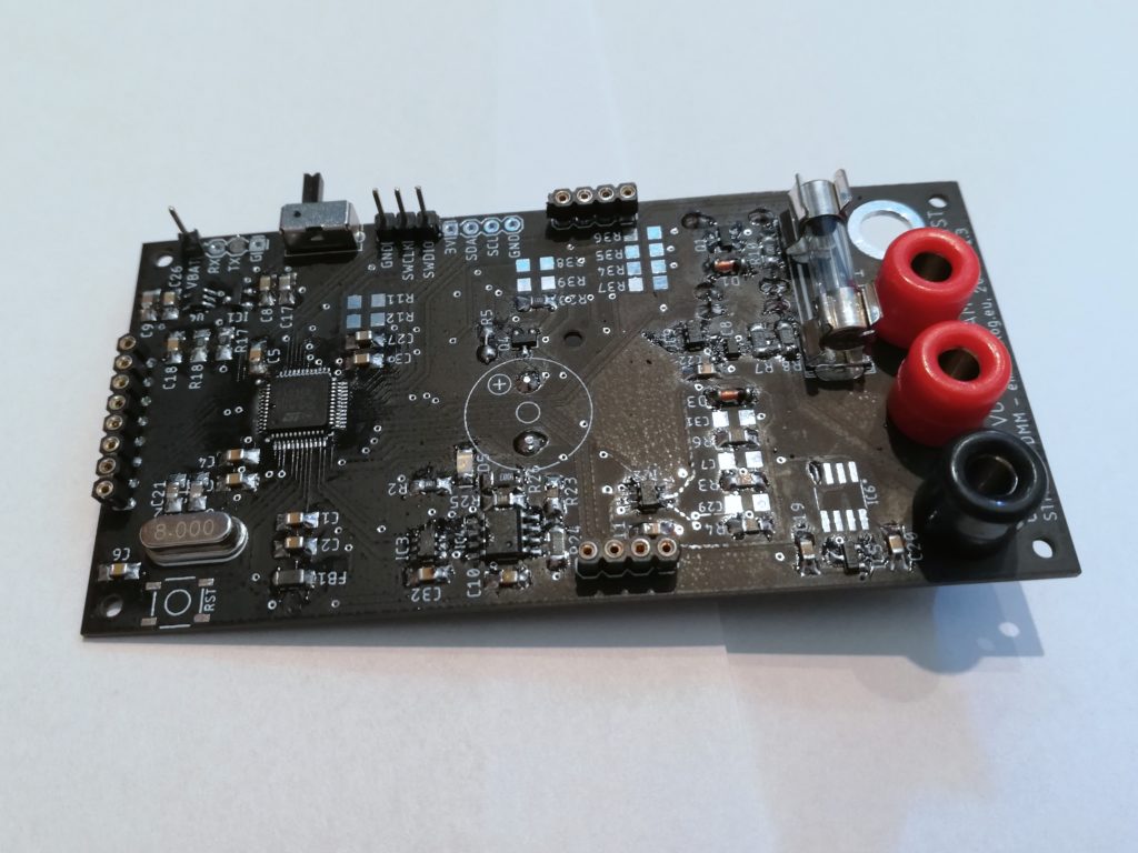
Yesterday, parts for revision 1.3 finally arrived and this meant I could start populating the PCB. I managed to populate and test it in just two days (which is unusually fast for me) and in this article I’ll explain all the changes to the multimeter. If you forgot all the features it already has, check out the short video about rev 1.2:
First, I’d like to make it clear that this revision is not meant as “production”, it is more like a “test platform” for the new analog front end. I mean it all works, but I did not design a case for it and also the software might still need some tweaks to update it to version 1.3 hardware. The main reason for this is that I am leaving in a few days (and I’ll be gone for three weeks) and I really want to order revision 1.4 PCBs. So if anyone is interested in building this – I recommend that you wait for rev 1.4, because I think it will be totally worth it.

Two more voltage ranges
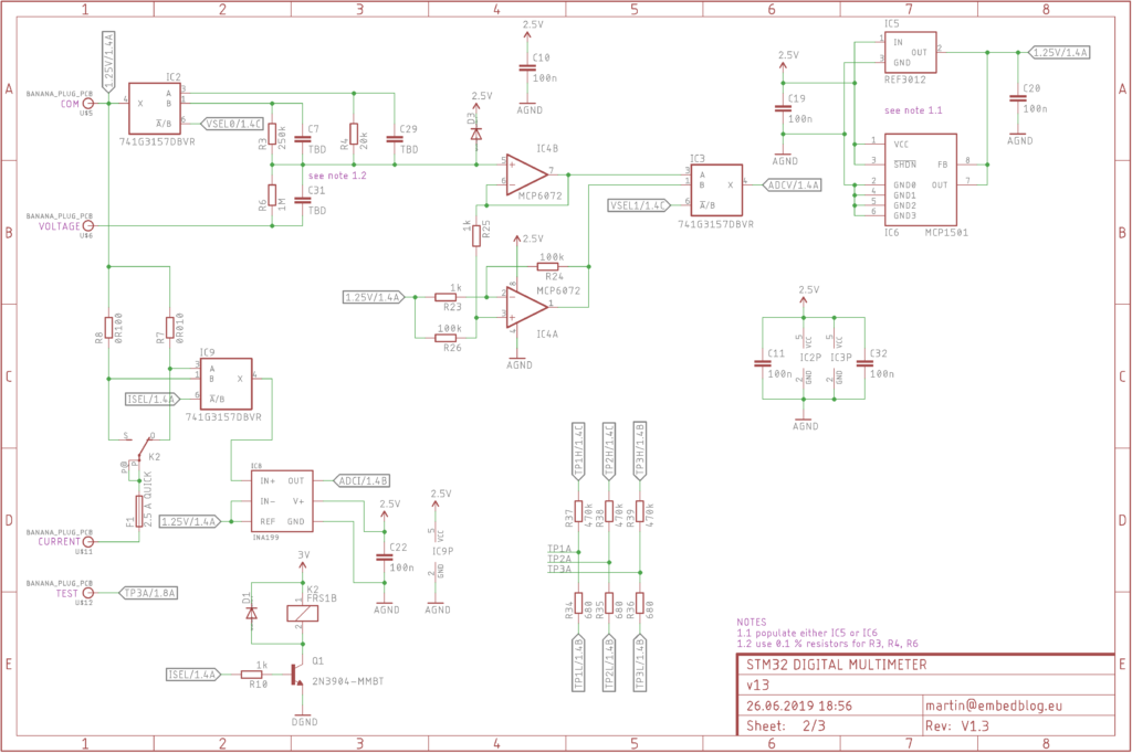
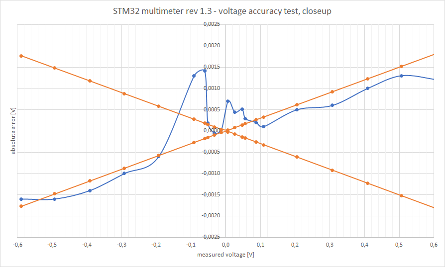
The biggest change, which I also explained in this log on Hackaday, is that there are now four ranges for measuring voltage in total: ±60 V, ±6 V, ±600 mV and ±60 mV. The upper two ranges have accuracy better than 0,3 %, the lower two are mostly within 1 %, see the graphs below. I know where the error on lower ranges comes from – it’s caused by the offset of the IC4A opamp, which gets multiplied by 100. Thankfully, the offset stays relatively constant, which enables you to compensate for it in software.

I consider these results pretty impressive, given how crude and cheap the whole device is. Again, my goal is not to compete with a 200 USD multimeter. But, on the other hand, the Brymen 805s costs 53 euros and has the same accuracy (0,3 %). And it has no RMS, no computer connection, no power measurement etc….
Totally reworked current stage
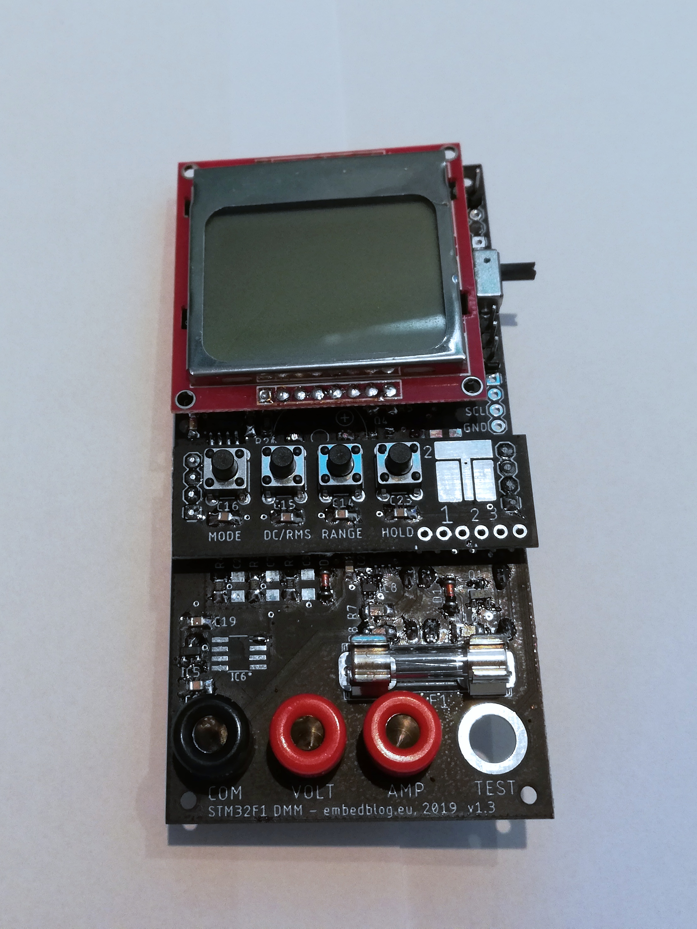
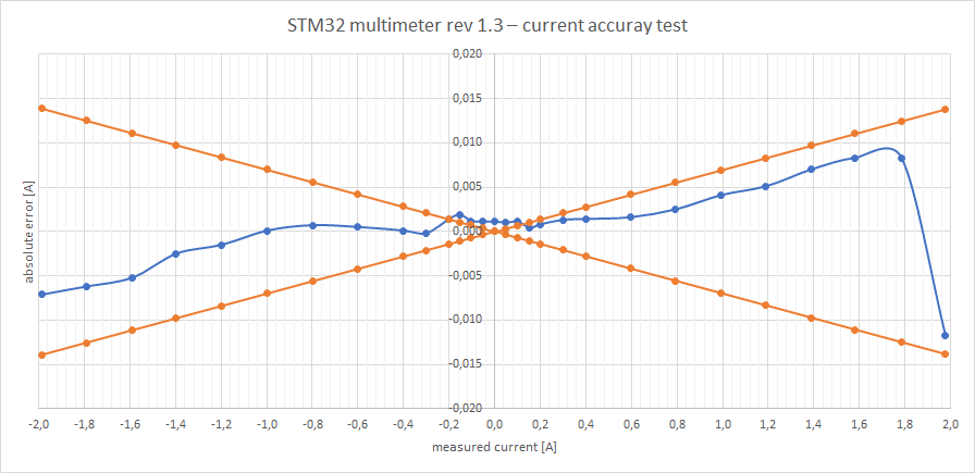
In the last revision, the current stage was still highly experimental, with a very limited usability (thanks to the low max current of only 500 mA and really high burden voltage on the very large 10 and 1 Ω resistors). Well, good news! I managed to improve both of these drawbacks. I am now using an INA199 differential opamp to sense the voltage across either a 10 or 100 mΩ resistor, so the max burden voltage on 200 mA range is 20 mV, which is on par with commercial multimeters and this also enables much higher ranges, which are now ±2 A and ±200 mA. And the protection is now realized using a a classical 5×20 mm fuse, instead of SMD-mounted one.
Software changes
What hasn’t changed much is the software, which is unfortunate, since it really needs polishing. However, as I said above, as of now the priority for me is to order version 1.4, which will require a rework of the software anyways. So as of now, the only change is that the DMM now remembers last mode you used (voltage, current, power, …) and also the range on each of these modes.
What’s next?
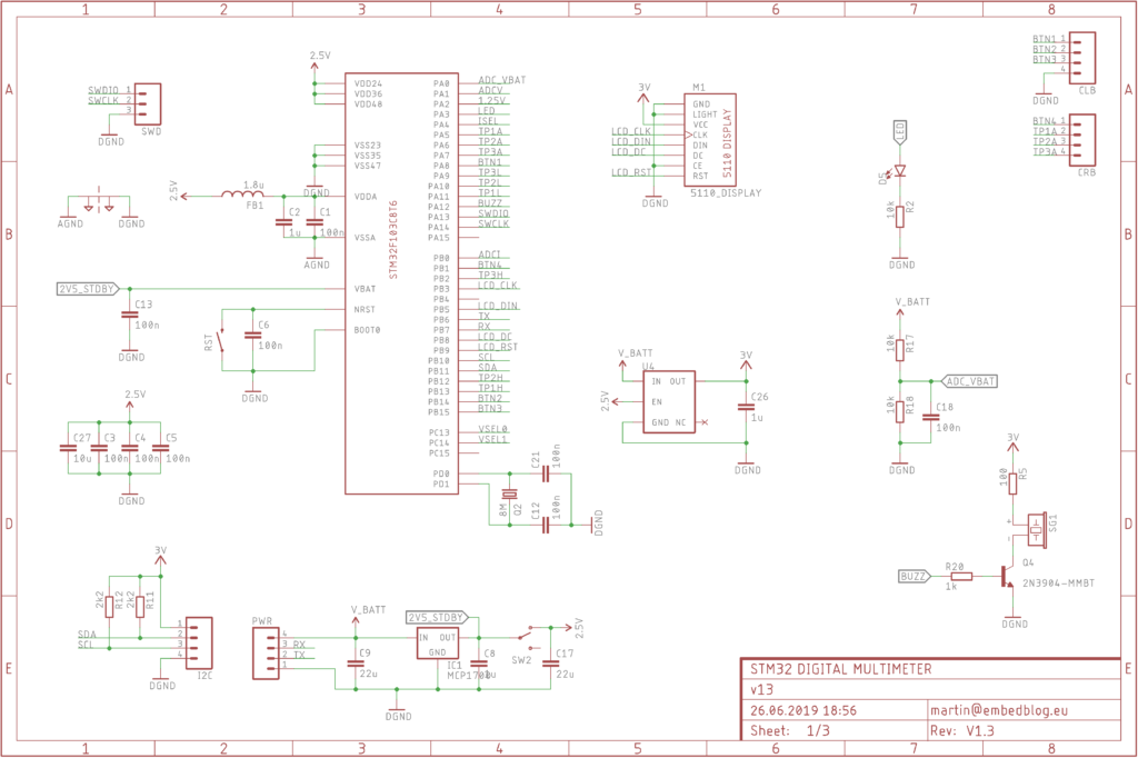
I have big expectations from the next revision – mostly because I am going to switch the microcontroller from STM32F103 to STM32F373. The F3 is from a line of microcontrollers targeted at analog applications, so it has three very important things, which I believe will greatly improve the accuracy and general performance of the DMM:
- 16 bit ΣΔ ADCs (so higher resolution than the 12 bits we are using right now)
- differential inputs (as of now, I am just subtracting the values in software, which of course doubles the error)
- dedicated analog reference input (so we won’t have to rely on the accuracy of the LDO regulator powering the chip).
Also the ‘373 has a more powerful core (Cortex-M4F) with a floating point unit, so this should do all the calculations faster. Finally I’m going to totally redesign the whole board.
Conclusion
When I released revision 1.2 about four weeks ago, I did not expect that so many people will find this interesting – this project was featured in a Hackaday weekly update, on Hackster.io blog, etc. I am very proud of that, but it is still not finished and there is a lot of work to do. But even so, I am pretty satisfied with the results we have so far. I’ve also been using revision 1.2 almost daily, without a single problem.
Now I am going to start working on revision 1.4, which I hope should improve performance dramatically. The expected release (take this with a huge grain of salt) is at the end of July.
Links
Test setup
Just as a final note – I’d like to explain how do I get all these fancy graph. As a reference, I am using a newly calibrated Brymen 867s, which has a DC voltage accuracy of 0,03% + 2d and current accuracy of 0,5% + 20d. The value I get from this meter is considered “correct” in my calculations. Then, I supply some waveform (in case of voltage, I use a FY6800 generator, in case of current, I am using my own construction) and measure this waveform with both the Brymen and my meter. This then gets compared and you can see the results on the graphs above.
Martin, are you aware there are commercially available DMMs that use this STM32, I have one here on test. I am interested in finding out how hackable it is. Please get in touch via Instagram EVMYT for a chat.
Hi,
well, I was not aware, that’s an interesting discovery. Would you be willing to share the DMM model?
Unfortunately I do not have Instagram, so I cannot get in touch that way… but feel free to send me an email at my address (see the Contact page at the top of this web).