
AVR-based Li-Ion battery charger
If you ever worked with lithium batteries, you probably know the TP4056 – a chip for charging lithium batteries with CC-CV profile, two LEDs for state-of-charge indication, temperature input and so on. You can find it relatively cheaply on Ebay or similar sites, either as standalone IC or on a small and very practical breakout board with a microUSB input. I also made an advanced version of one of these boards.
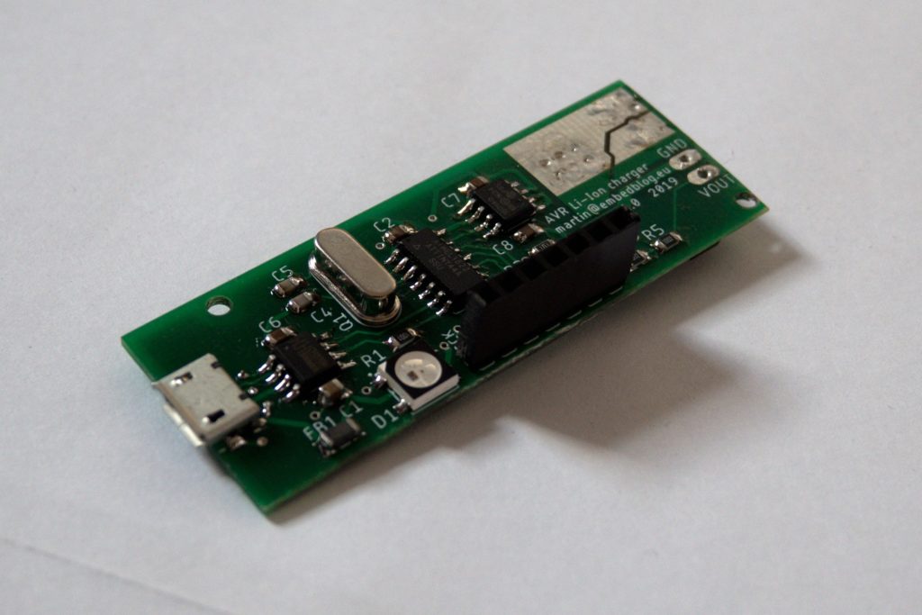
However, it is not configurable – it’s max voltage is fixed to 4.20 V and the charging current is set with a resistor. But what if you want to charge one of these ‘Li-HV’ cells, which have a Vmax of 4.35 V? Or what if you want to do a “storage charge” to only 3.9 V? Or what if you need to change the current? Changing the resistor every time you want to change the current is not very practical…. And since I work with lithium batteries a lot and I often need some of the things above, I came up with this board:
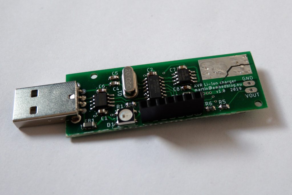
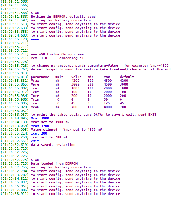
It’s a buck converter controlled by an ATtiny44 with software adjustable voltage and current limiting, cutoff current, precharge current, min and max temperatures and so on. These parameters are stored in the ATtiny’s EEPROM and it is very simple to change them, because another IC on this board is the CH330, which is a variation of the well known CH340 USB-to-UART converter, just this time it’s in an SO-08 package. So what you do is you plug this into your computer’s USB and fire up a serial terminal (I use YAT) with a baudrate of 19200 and voilá – a configuration portal shows up. Then you can change any parameters according to your needs (see the picture below). After you unplug the board from the USB, connect a battery and plug this into a powered USB (like a wallwart) and it starts charging according to the presets in EEPROM.
Principle of operation
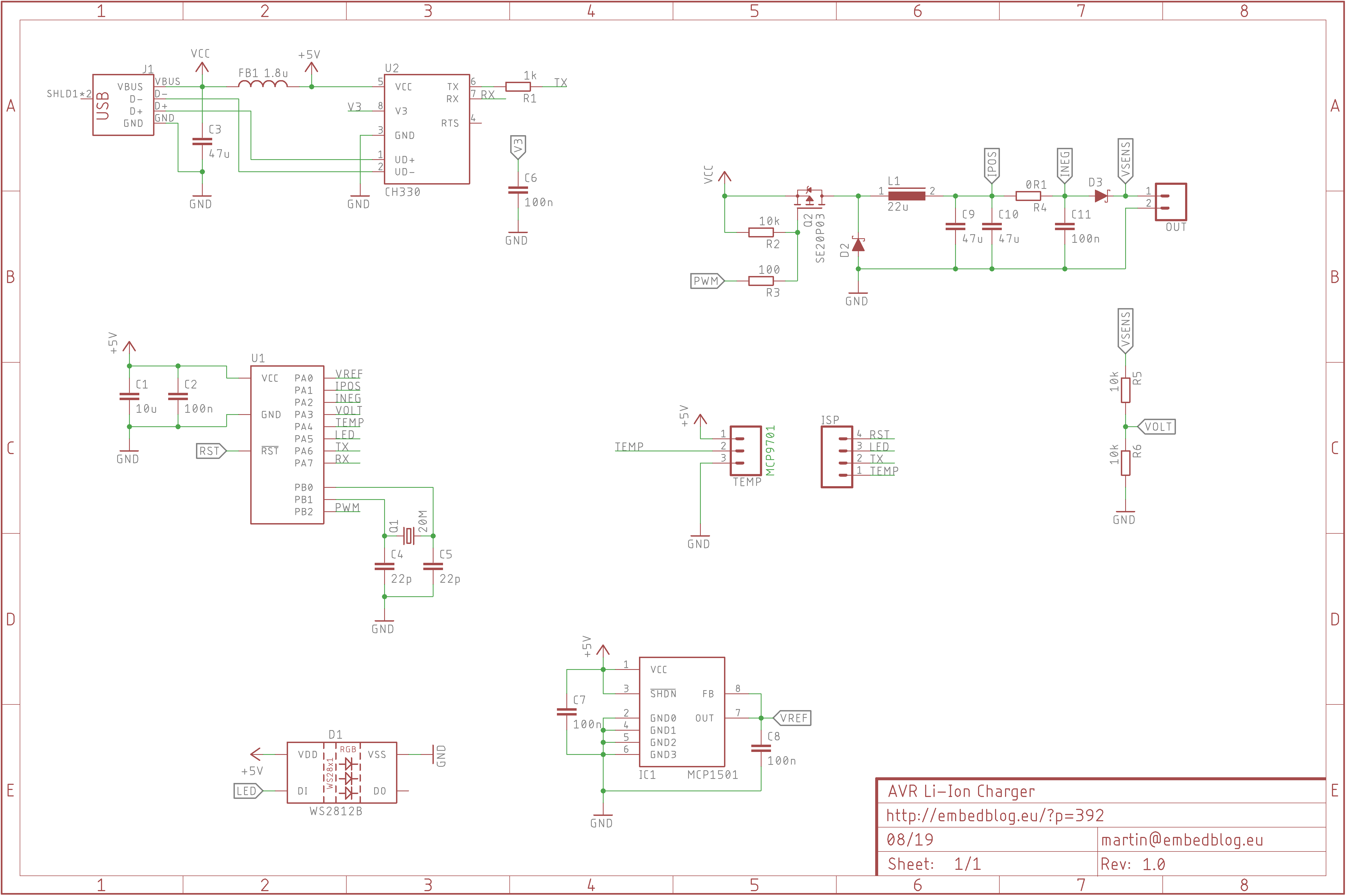
My goal was to keep this board as small as possible while maintaining usability, so the topology of the buck converter is really simple. The ATtiny drives the gate of a P-channel FET directly with an inverted PWM signal. Because of size, I wanted small inductor and capacitors, which means as-fast-as-possible PWM. For this reason, the ATtiny is clocked from a 20 MHz crystal, which results in a 78 kHz 8-bit PWM.
The analogue part has two nice tricks. Firstly, when most people measure something with the ADC on, let’s say, an Arduino board, they use the AVCC as a reference – this means that the +5 V from USB is used as the top of the ADC range. However, the USB was not designed to be used as an analog reference, and it is very imprecise and noisy. And for charging lithium batteries, you need an accuracy of about ±50 mV, which means I had to utilize an MCP1501 – a 4.096 V reference, connected to PA0. This is the first trick – the ATtiny’s pin PA0 can be configured to act as an AREF for the ADC. Also, with a 4.096 V reference and a 10 bit ADC, one LSB is exactly 4 mV, which makes calculations much easier for the CPU.
Another thing – about which not many people are aware – is that the tiny44’s ADC has differential inputs with selectable gain of 1x or 20x. This is how I did the high-side current sensing without any additional components – a simple 100 mΩ shunt resistor is sensed by a differential input with a gain of 20. So the full scale current is 2 A, which is also the max output from a USB port. So everything fits together nicely.
Since I had only one IO pin left, I had to use a WS2812 “smart” LED for signalization. Once the device is plugged into USB, the LED start blinking blue. Now if the user connects a battery, the device switches to charging mode and starts charging, according to the parameters. However, if no battery is connected and the user send anything to the device via serial, it switches to configuration mode and prints the configuration portal. Here, the user can change any of the parameters listed, as long as it is withing given margins.
Here are short explanations about the charging variables
| Variable name | Description |
| Vmax | Maximal charging voltage of the battery. Usually between 4.1 to 4.35 for lithium cells. |
| Vpre | If the battery has lower initial voltage than this, the charging process will start with a precharge, which is a slow charge intended for batteries with undervoltage. |
| Imax | Maximal charging current. This also limits how much current will be drawn from you USB (in case you have just 1 A USB sockets, for example). |
| Icut | Cutoff current – once the charging current drops below this value, the charge is considered finished. Usually set to 10 % of Imax. |
| Ipre | Precharging current – if the battery goes thru precharge, this current value will be used. Usually set to 10 % of Imax. |
| Tmin | Minimal temperature for charging. |
| Tmax | Maximal temperature for charging. |
| Vcon | Once the device is plugged in, it starts monitoring the output. If a voltage higher than this appears on it (because even a discharged battery still has some voltage), it starts the charging process. |
State of charge indication
Of course I wanted to be able to tell the current stage of the charging process without using the serial monitor. The most convenient way is probably with LEDs, however since I had only a single pin left, I had to use the WS2812, which is an RGB LED with an integrated driver. Slightly overkill, sure, but in the end it enables a lot of colors:
- blue blinking – waiting for the user to connect battery or initiate configuration mode (by sending anything over UART to the device)
- blue on – configuration mode
- purple color – precharge
- red color – constant current
- orange color – constant voltage
- green color – charging finished
- red blinking – error (temperature too low/high)
Possible future updates:
- micro USB input
- (Arduino-like) UART bootloader, so that the firmware can be changed without using a dedicated programmer (with this, you could for example upload firmware for charging NiMH batteries just by plugging it into USB)
- it would be interesting to make the LED change colors gradually from purple to red to orange as the charging process progresses
- add charging timeout
Notes
- Since the code takes 4076 bytes out of the 4096 available (that is 99.5 % of the program space) on the ATtiny44, it’s important to set the -Os flag (optimize for size) in the Makefile/project properties. Otherwise, the code will be too large to fit onto the MCU.
Update 09/2019
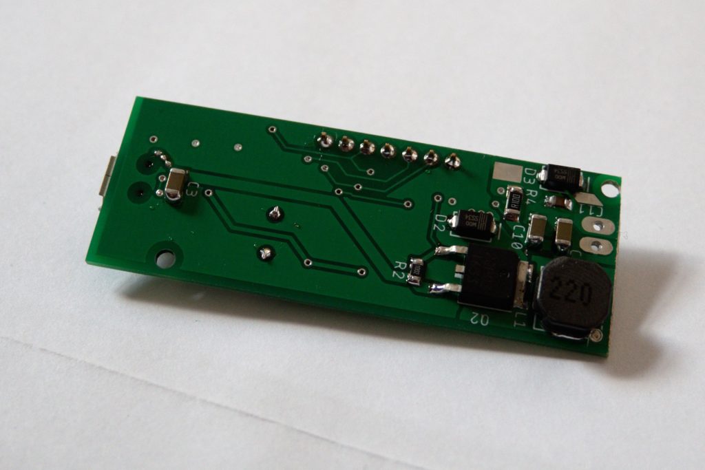
After using the device for a while, I’ve made a few changes – firstly, the code has been optimized, so even with some small features added it now takes up only 3886 bytes. Other changes include better thermals for the FET, inductor and (most importantly) both of the diodes, mostly in form of larger pads with more vias. I’ve also made a microUSB version. And lastly, the processor now automatically detects wherever the temperature sensor is present or not, which enables operation without it (as the cable with the sensor is kinda clumsy and gets in the way all the time, so I made it removable).
Some people sent me requests to buy these things, so I put both versions on Tindie.
Conclusion
Another handy gadget I have been using for a few months now. The programming was surprisingly challenging, given the relative simplicity of operation.
As always, all source files are on GitHub.
Really nice project!!
Ahoj!. Since input to output voltage difference is pretty small, one could use linear regulator instead of DC-DC converter. I would use a better microcontroller like STM32.