My Open Source Multimeter – final revision
Update 04/20: development has been restarted with a new version coming! See here.
So I finally arrived at the point where I consider my Open Source Multimeter finished. It is not perfect, but it is more than good enough for my purposes and I also do not have time to develop it any further (at least for now). So in this article, I’ll descibe what I came up with from the ground up, since it might be hard for some people to keep track of all the changes (so this article might include parts from the previous blog posts). This time, I’ll be keeping this post updated, in case some small changes come up. So without further ado, here’s an updated video showing the DMM in action:

Why?
Long story short, I needed more multimeters. So I set myself a budget, made a list of requirements and started shopping.
After searching for a long time, I was disapointed, as I wasn’t capable of finding a single multimeter which would fullfill the above list. So I decided to try and design a simple multimeter for myself. It took a lot of time, but I am really glad that now I have a fully usable multimeter (and I am building three more for myself). Of course this cannot compare to a 200 dollar Fluke, but that’s not the point, really. But I’d say it is superior to a cheap Chinese multimeter from Ebay, and a datasheet below (which I will hopefully make in the next week) will show you it can even compare to a 50 Euro Brymen multimeter.
Just a disclaimer – you have probably noticed that there isn’t a range for AC mains voltages – and there are good reasons for that. Firstly, I just wouldn’t feel safe working with mains with something I made at home and secondly, all these CAT ratings would impose a lot of limitations on the multimeter. And lastly, I cannot even remeber the last time I measured mains, so I think I just don’t need such a range.
Features
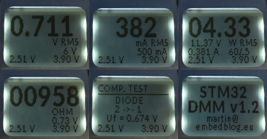
Since the start of this project there have been 6 “modes”: voltage, current, power, continuity, component test and frequency (this was actually added in the last revision). Simply said, it can measure:
- voltage, with a 16-bit ΣΔ ADC. There are four digitally selectable ranges: ±60 V, ±6 V, ±600 mV and ±60 mV. All of them support either DC (ie. average) or RMS (ie. effective) value (note that it is trueRMS, so it works on all waveforms, not just sine). Of course the inputs are protected against overvoltage
- current, again with the same ADC. There are only two ranges – ±2.5 A and ±250 mA. It might be possible to implement another current range, ±25 mA, in software, as there’s a PGA present, which is not used as of now. Again, both RMS and DC values are measured.
- power, which is simply a product of both voltage and current. But the screen shows the raw V & I values as well. You can use all 8 possible combinations of voltage & current ranges – but to set the range, you need to go to the voltage/current screen, set it there and return back to the power screen. It is not very convenient, but I just haven’t found an intelligent way to do this with just a single button.
- continuity – as of now, it’s simply a 220 ohm resistor connected to +3V on one side and TP2 on the other side. The DMM then measures voltage on TP2 and calculates resistance. A buzzer is sounded when resistance is below a configurable threshold.
- component test – can test resistors, diodes and capacitors. You can either use the pin header for THT components or the SMD test pad (this is actually handy, if you have for example SMD capacitors, which are not marked)
- frequency – the wave is fed into a 32-bit timer, which is then read every second. As of now, the max amplitude of the wave is 3 V, but this could be easily extended using a simple zener diode.
Expansion port
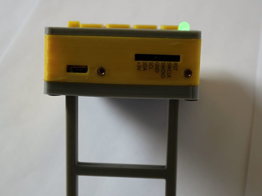
I’ve also included a header which extends to the top side. It can either be used for programming/debugging or as a 4 bit IO (alternatively, two of the IO’s can also serve as I2C or UART). My idea is that you can plug in something like an expansion module, with for example thermocouple amplifier or SD card writer.
Accuracy
Of course a multimeter would be useless if it wasn’t showing accurate information. Initially, I was hoping to avoid calibration, but there are just too many variables. But after a really simple 5-minute calibration, these are the results you can achieve (all results are measured against my Brymen 867):
| Range | Accuracy |
| ±60 V | ±0,1 % ±4 LSD |
| ±6 V | ±0,1 % ±5 LSD |
| ±600 mV | ±0,1 % ±7 LSD |
| ±60 mV | ±0,1 % ±2 LSD |
| ±2.5 A | ±0,3 % ±30 LSD |
| ±250 mA | ±0,1 % ±6 LSD |
And here’s a gallery showing all the accuracy charts (orange lines represent the accuracy margins):
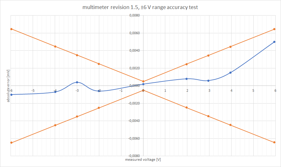
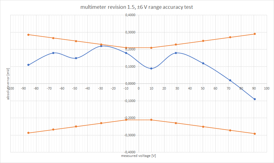
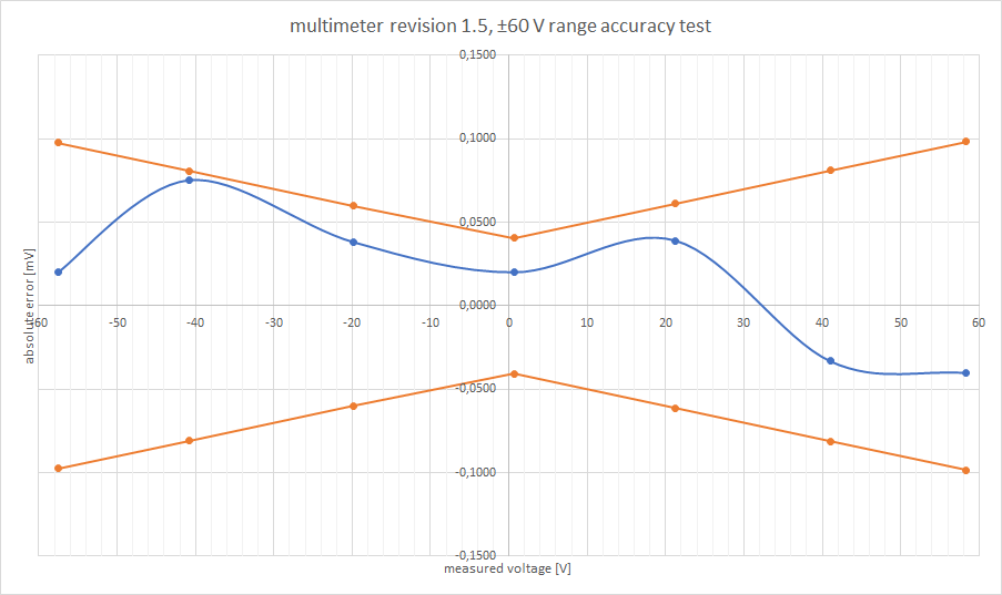
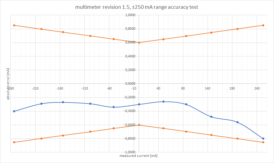
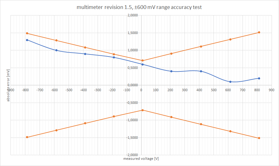
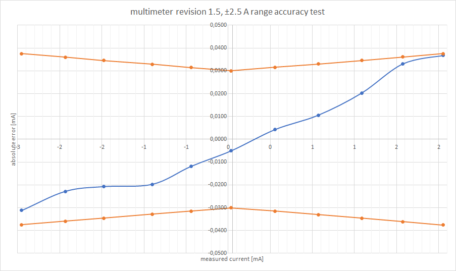
I am planning to do some more test (temperature stability etc.), but from the gallery above you can tell that with a more carefull calibration, you could probably get even better results.
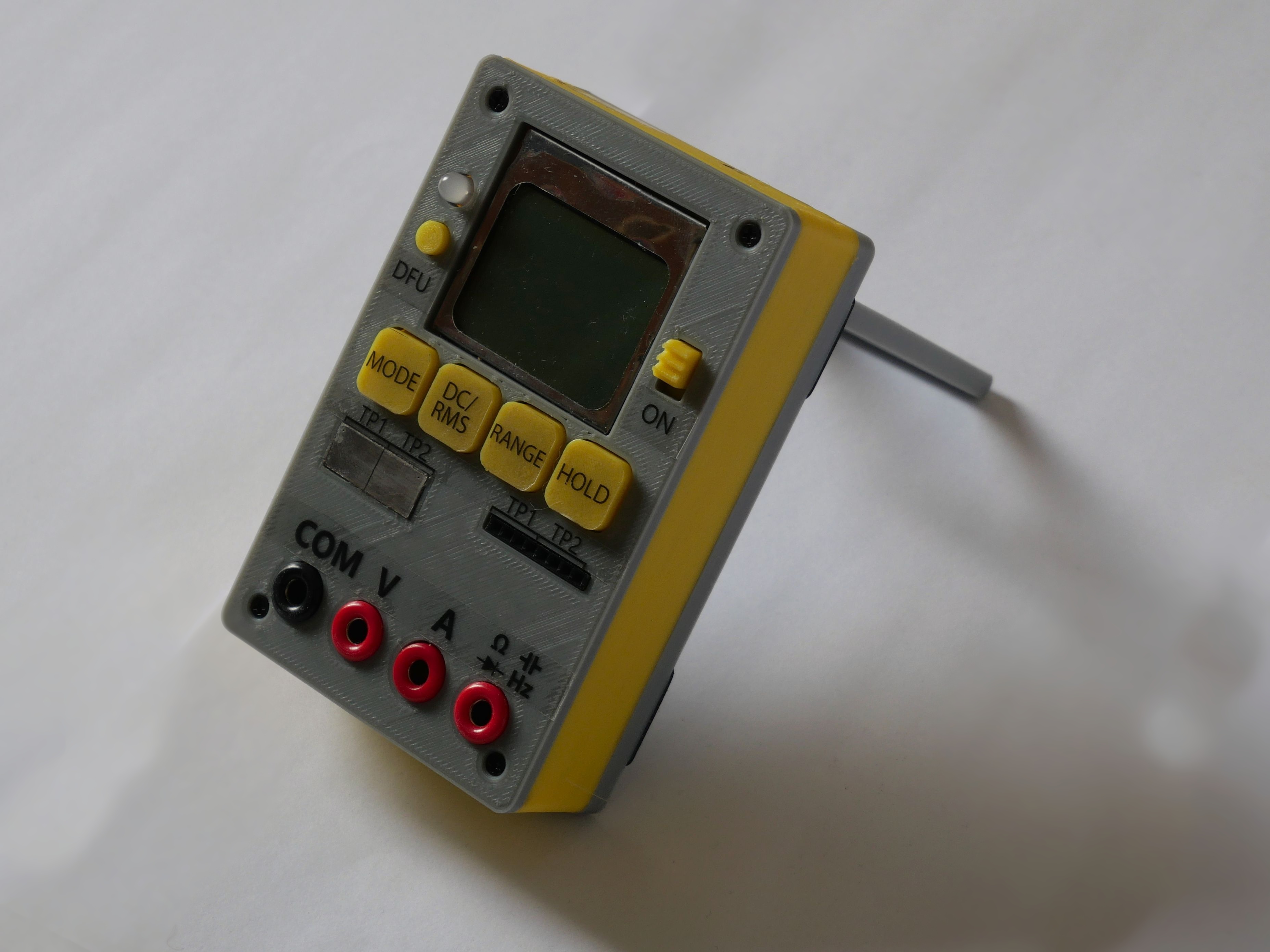
Construction
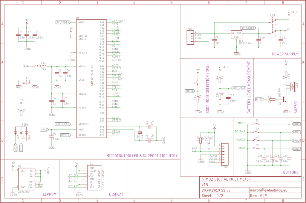
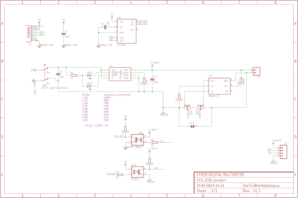
The multimeter consists of two PCBs – one with the DMM itself and the other one contains the USB interface, battery charging and protection circuit. Both of them fit well into a 100 x 100 mm PCB order, which is something I really wanted, since that allows you to order the PCB really cheaply from China.
There is a lot of components on the main PCB, but most of them are passives. The footprints are 1206, even though I prefer to populate 1206 footprints with 0805 components. There are only two tricky ICs to solder – the main processor (STM32F373CCT6 in LQFP48) and the INA199 in SC-70-60 package. But otherwise it is pretty simple to assemble the board.
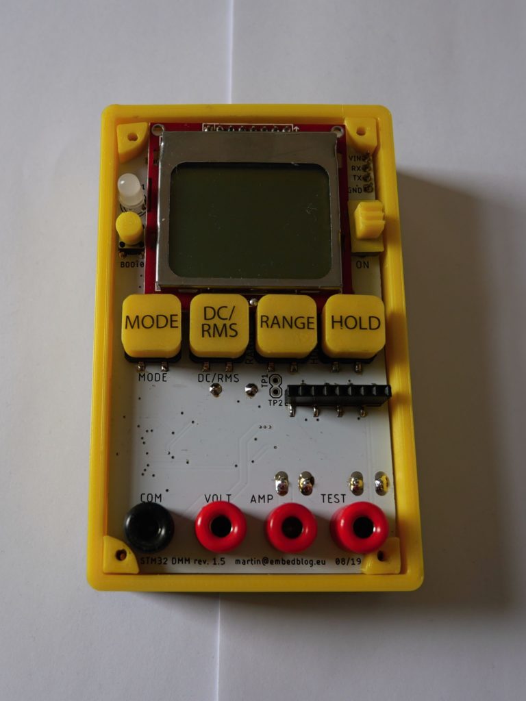
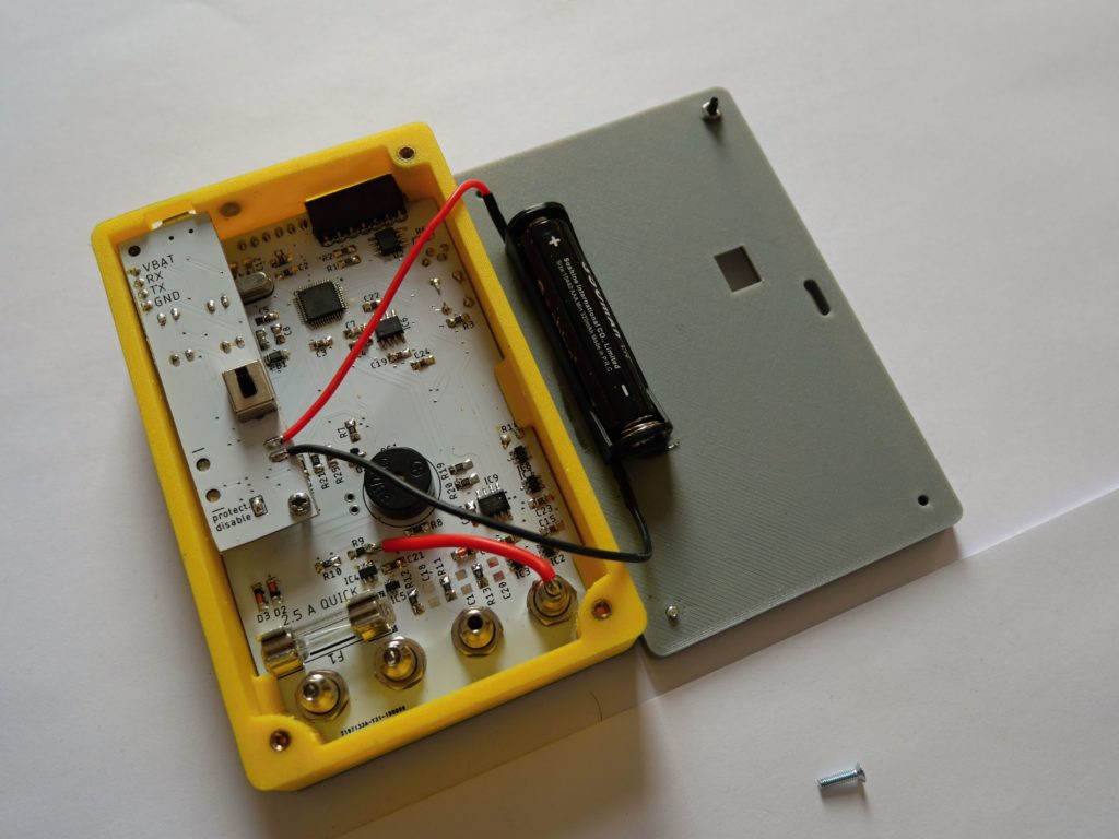
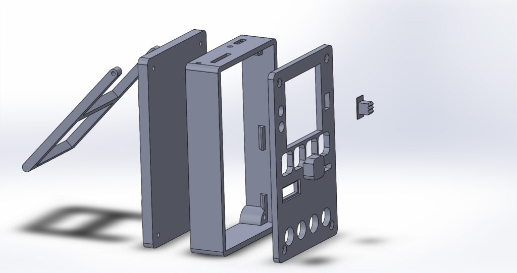
The whole case is 3D printed. It consists of a lot of parts, which are screwed together with various M2 screws. I also used brass insert nuts, but I am not sure if I won’t remove these in future cases I’ll print, since inserting them is a lot of fuzz and frankly, they are just not needed.
Another challenge I faced was how to put fine print onto the 3D printed part (button names, port names, etc.). In the initial release, I used normal paper, onto which I printed the labels and then superglued it to the case. The good thing about that was that it stuck well to the case, but it looked ugly. In this revision, I used self-adhesive transparent foil, which looks much better. The glue isn’t the strongest, but it hasn’t come off so far.
Possible upgrades
The hardware behind this prokect is really powerful. Unfortunately, I am more of a hardware guy and so there is a lot of features, which are supported in hardware but not yet implemented in software. Here’s a list of them from the top of my head (this is also something like a ToDo list):
- true autoranging
- additional current range (should be possible with the current hardware)
- better serial control
- some modules for the expansion port – thermocouple amplifier, WiFi/bluetooth interface, SD card
- there’s a built-in DAC (available at TP2), which could be used to produce some reference waveforms of some sort
- mAh, mWh logging
- measuring real/reactive/apparent power and cos ϕ
- improvements to the continuity/component test, so that they utilize all 6 available resistove dividers
Featured on
Here’s a short list of pages where this project was featured, discussed or so on.
- On The Amp Hours podcast
- On Hackster.io
- In the weekly Hackaday.io email newsletter on June 5th, 2019
- Someone started a thread on Hacker News
- And also on Arduino for STM32
What I never realized before I started publishing my projects is how much extra work that is. One thing is to make the whole project/thing/board etc., but then it takes a whole lot of time to make it ‘publish-able’, to write documentation and so on. So I am always glad when it is time well spent and people read or discuss it.
Conclusion
I am really happy that I managed to get this into a fully usable state and it didn’t end up like a lot of other projects on the internet (that is, abandoned in the middle).
I have been using different revisions of this project daily and I haven’t had any major problems. Of course, there are still bugs in software and the ToDo list above is quite long.
All of the files are available on my GitHub under CC BY-NC-SA 4.0 license (Attribution-NonCommercial-ShareAlike 4.0 International). The 3D files for the case are also on Thingiverse.

History of updates:
2. 10. 2019: added case render & Thingiverse link; added ‘Featured on’; slightly restructured links;
Do you have any PCBs for sale?
Well, I have blank PCBs, but I think it would be cheaper for you to just order it manufactured in China…
Hello
I’m building a true RMS voltage measuring school project.
Can you help me?
Please send a message to my email
Hi,
feel free to post your questions here or send them to my email.
Regards, M.
Can you give me your email?
Hi,
there’s a section called “contact” on the top of the site… there you can find it.
I was thinking, this is an interesting project and looked into the cost of building.
Total cost BOM itself became prohibitive. A 5110 LCD module here in India costs about 200 rupees. For this price I could buy a cheap chinese DT830 multimeter.
My opinion is it has the potential to become a great project if some of the TODOs are implemented and the CPU replaced by a cheaper version.
Hi,
well, this is more of a technological demonstrator than, so comparing it to a cheap chinese multimeter is pointless, I think. Also those 5110 screens are really cheap on Ebay. And since the accuracy is relying on the SDADC in this particular MCU, I’m afraid replacing it won’t be that easy…
Hi Martin,
Your project is amazing.
As a beginner in electronic, I would like to build such a multimeter (this version or the new one).
I opened the GitHub files into Kicad, but :
– I cannot get the complete list of components I have to buy (some resistance or capacitor values are missing, some components are not defined enough to help me identifying the good one to buy)
– I struggle to understand how to generate a file to produce a PCB (but it is my job to find how to do it with Kicad…)
All in all, thank you for sharing your work, it has so much value for me!