3D printing a stencil for applying solder paste
If you ever tried making more than a couple of the same PCBs at once, you probably came to the conclusion that soldering it by hand sucks and also takes a lot of time. The alternative – which is also how they do it commercially – is the so called reflow soldering. Simply said, it has two steps – first, you apply solder paste on the pads and then put parts on their respective positions. After that, you reflow the board (either on a hot plate, using hot air or in an oven) and you are done.
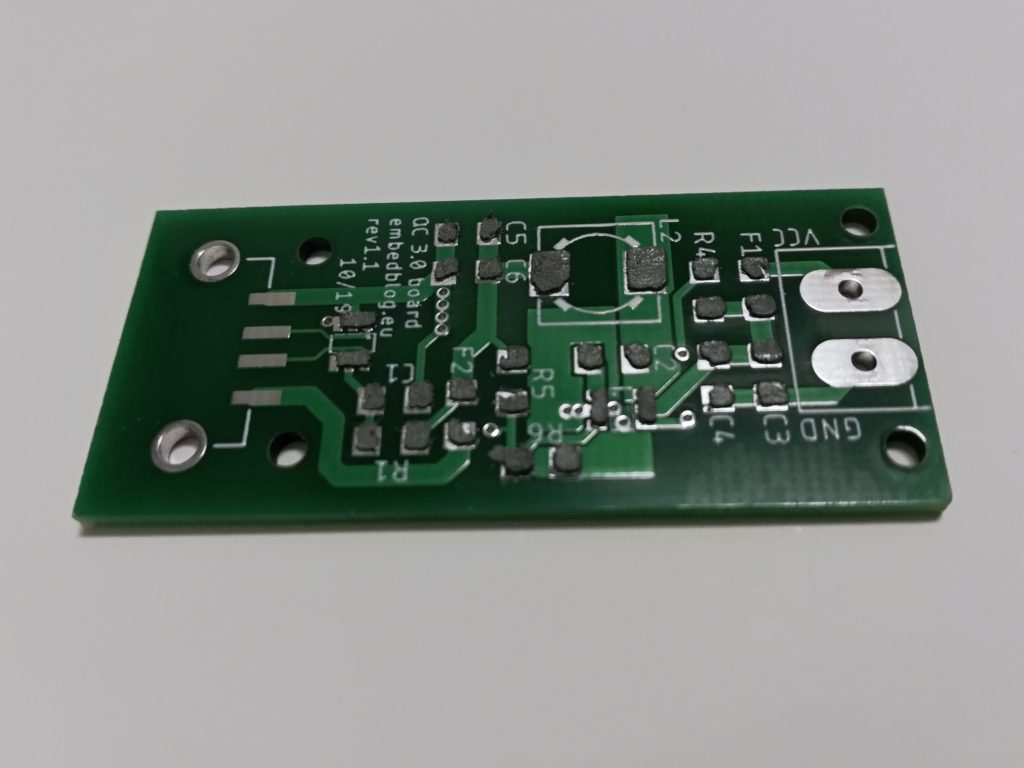
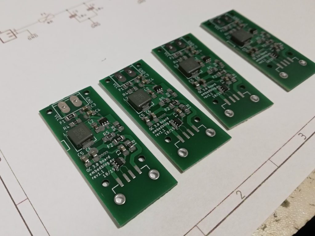
Recently, I decided to make 10 of my Quick Charge 3.0 boards (which I am selling on Tindie), and I really wanted to avoid having to solder 10 of the same boards by hand. So I decided to use reflow soldering. Basically, you can put the solder paste on the pads either by hand (which takes a lot of time and effort) or with a stencil. These stencils can be bought from China for about 10 dollars, but it takes some time to arrive and the shipping is usually expensive. So I decided to 3D print myself a stencil and in this article, I’ll show you how I did it (there is also an alternative way – see Conclusion).
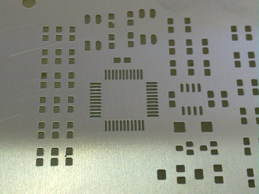
Commerical stencils (see above) are usually thin steel or polyimide (Kepton) sheets with lasercut holes. The thickness varies, but usually it is about 0.1–0.2 mm. My Ender 3 Pro can print at about 0.07 mm minimum layer height, so I can fit two layers, each 0.1 mm (it is really tricky to have a first layer with a .07 mm thickness).
Step 1: export DXF from Eagle
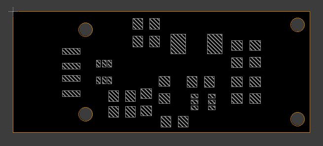
First, you’ll need to open Eagle and turn on only layers “Dimensions” and “tCream” or “bCream”. Then hit File -> Export -> DXF and save the file. Make sure to note units used (in the bottom left corner) – it will either be mm or inch.
Step 2: import to CAD
I think that any CAD program should be capable of opening DXF. I personally used Solidworks, so the how-to will be written for that.
In a new part you need to select a sketch or a plane. Then, while having this selected in the part tree, I clicked on Insert -> DXF/DWG and navigated to the file I created in step 1. A dialog will show up:
- in the first window, select “import as 2D sketch” (should be selected by default), then click Next
- in the second window, select the units you used in Eagle and leave the rest
- in the third windows, leave everything as is and click Finish
After this, Solidworks will show a message, asking for something about blocks. Just hit “No” and you should have the board outline imported into the sketch.
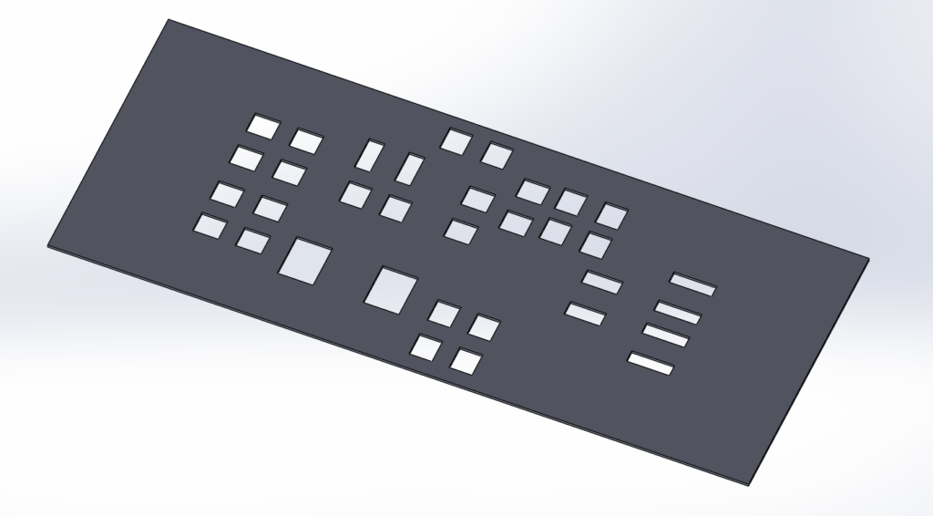
The outline will be blue, meaning that the distances are not defined. Simply said, you don’t need to worry about that. The only change I did to the outline is that I removed the screw holes and also merged the three small rectangles on each side of the SOT23-6 packages into one larger rectangle. After that, I just extruded the whole sketch to 0.2 thickness. This is what you should have:
The only remaining modification (which is not required, but recommended) is to add a notch on two sides of the stencil in order to prevent it from moving on the PCB when you are applying solder paste.
Step 3: 3D printing
After you are finished in Solidworks, export the file into STL. This can be then opened in Cura (or any other slicer software for that matter).
It took me a few tries to get a working result, so here are some of the most important settings I used:
- layer height: 0.1 mm (including initial layer)
- initial layer speed: 15 mm/s
- equalize fimalement flow: on
- combing mode: within infill
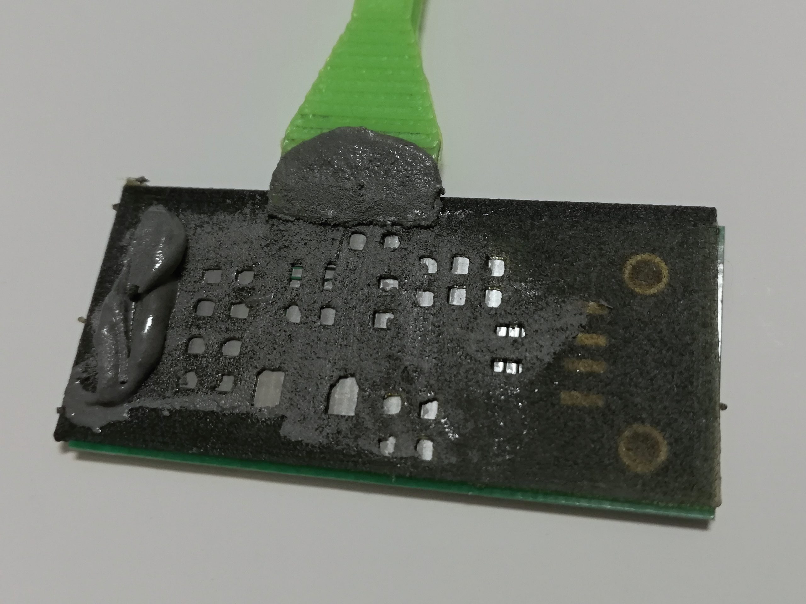
After printing, I sanded the whole thing down slightly with a fine sandpaper and then cleaned it using alcohol. Finally, I printed a spatula I found on Thingiverse and I was done! I’ll not describe how to use the stencil, because that’s the same as with a steel one. The only difference I noticed is that on the first pass with this stencil, it “soaks” some of the solder paste into itself – it is not really a problem, but I think it could be avoided by applying clear coat onto the stencil.
Conclusion
After reflowing, I only had to do minor repairs with a soldering iron, so I consider this whole endeavour a success. Even the SOT23-6 package was most of the time without any bridges, but I’d say that this is as small as you can get – a TSOP would probably not be possible. But maybe with a better printer and/or some tuning, you could make even that work.
A very good alternative, if you do not want to mess with Solidworks, is to use the page solder-stencil.me. It is basically a web based tool which turns your Eagle files directly into STL. The only disadvantages are the lack of customizability and also sometimes, the web is down and unaccessible.
You had a great idea! Hope that one day it’ll be possible to print stencils for smaller footprints! For the spatula, I’d rather use a phone card or expired credit card 🙂