Building a 100 W electronic load – part 1
Since I work a lot with batteries and power supplies, I often need to test them, usually by loading them with different currents. While you could build a high power resistive decade (out of 1 and 10 ohm resistors – I did this when I started with electronics), an electronic load will give you much more flexibility.
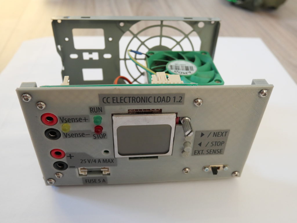
I’ve actually built such a load about a year ago and I’ve been using the version 1.2 since then. I started this build in 2017 as one of my first larger projects and also one of the first projects using STM32. It went thru 3 hardware revisions and I finally finished it in the beginning of 2019. It’s a simple electronic load with some UI, internal/external voltage sense, UART connectivity, temperature controlled fan and other support circuitry. The software also has some additonal features – it supports battery testing (with adjustable cutoff voltage), the current can be adjusted on-the-go and it also supports “load testing”, in which the current slowly steps up to a predefined level (useful for making efficiency charts or just seeing what your powersupply can handle).
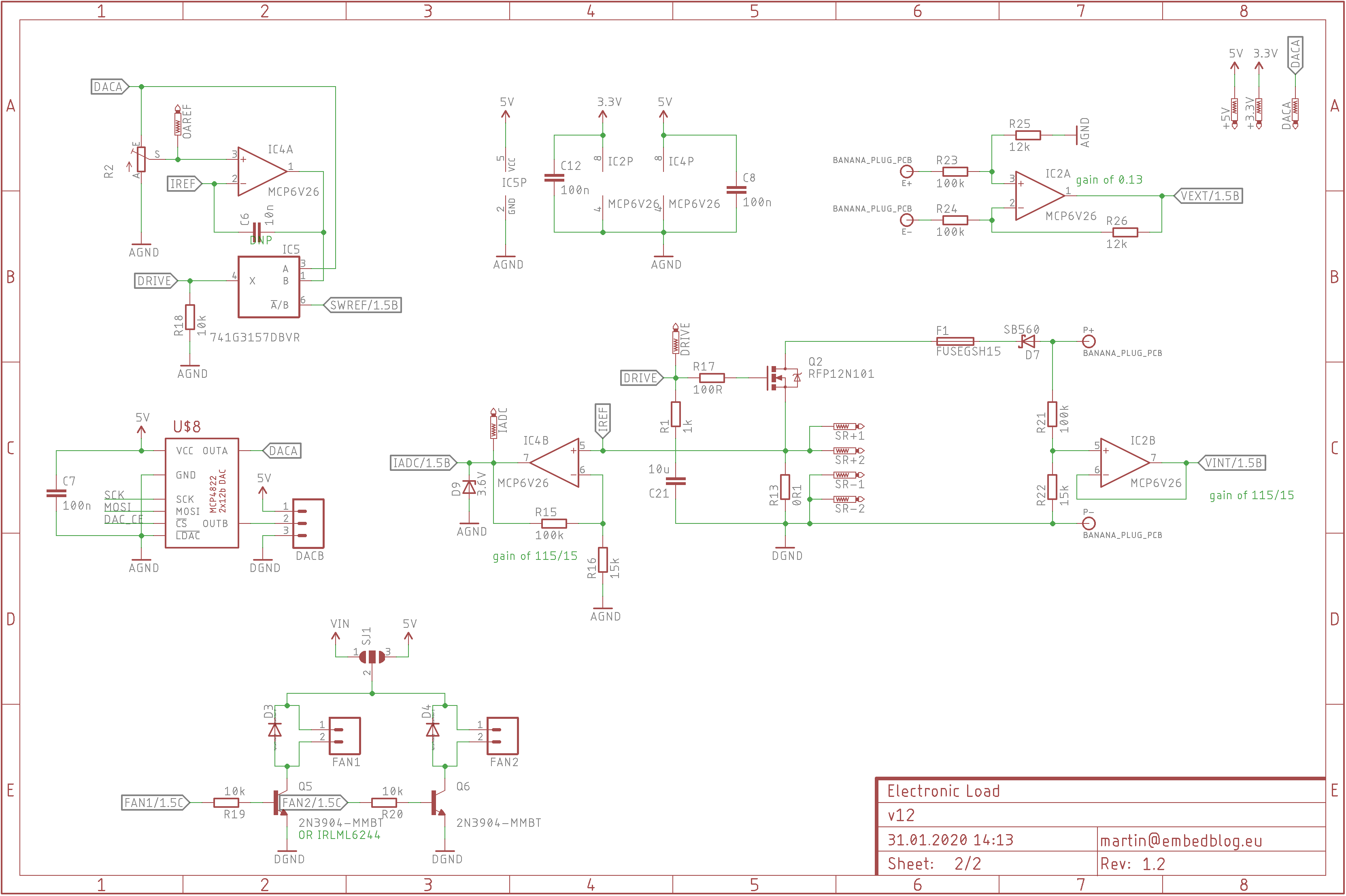
It actually works really good (and is also relatively accurate after trimming), the only two downsides is that the Nokia 5110 display often doesn’t make good contact with it’s baseboard and you need to push it or reset the device (this is a common problem of these displays, see here). The other being the fact that the fan on the heatsink makes ridiculous noises – I don’t know if I somehow damaged it or the bearing or what, but it is just unbearable. If anyone’s interested, here’s the schematics:

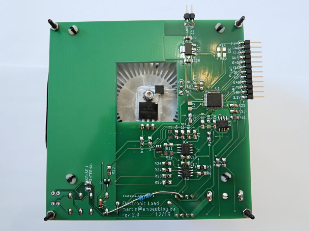
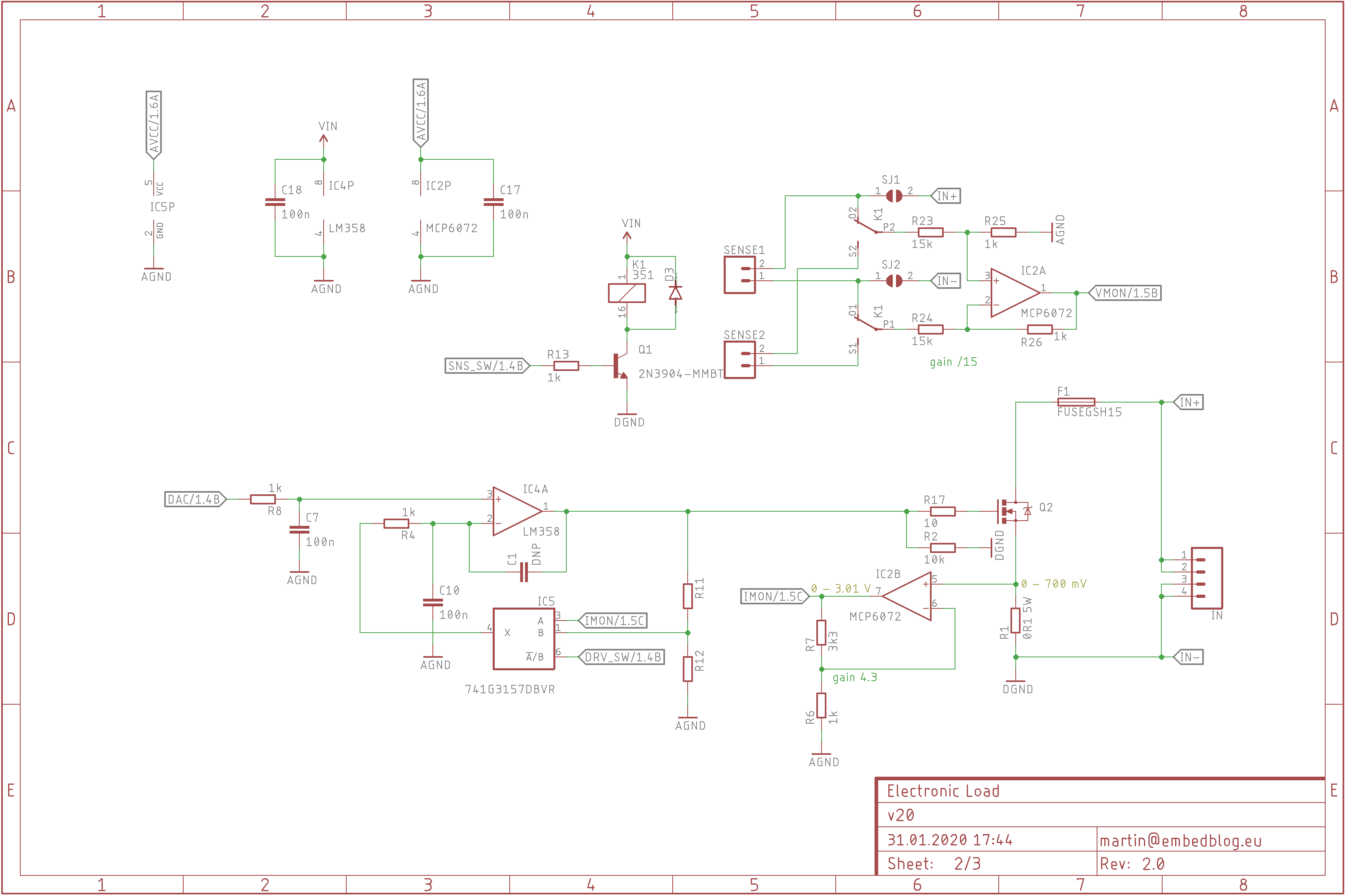
This old electronic load – which I call revision 1.2 – is nice, but after building my open source multimeter, I realized the potential of the STM32F373: it has much more precise SDADC with external reference and built-in DAC. And since I needed another load for my lab, I decided to start from scratch and design another revision – called revision 2.0 – based on the F3. Here’s what I came up with:

The design philosophy is slightly different – instead of trying to make one board with both the UI (display, buttons, etc.) and the power electronics part, I decided to make two separate boards – one with all the UI and the other with the heatsink and load. Each has it’s own processor and they communicate via UART or I2C. While it might seem unnecessary, this has some major advantages in my opinion:
- modularity – I can use the load without any UI (just connected to a computer via UART) or I can connect two loads to one UI module
- reliability – if I make a design mistake on one of the boards, I’ll need to redraw/remake only one of them
- and I am also currently developing two more lab instruments, which will use the same UI board as the load
The disadvantage is, of course, that you need two processors instead of one – but hey, with the prices of MCUs these days, that’s really not a problem in my opinion.
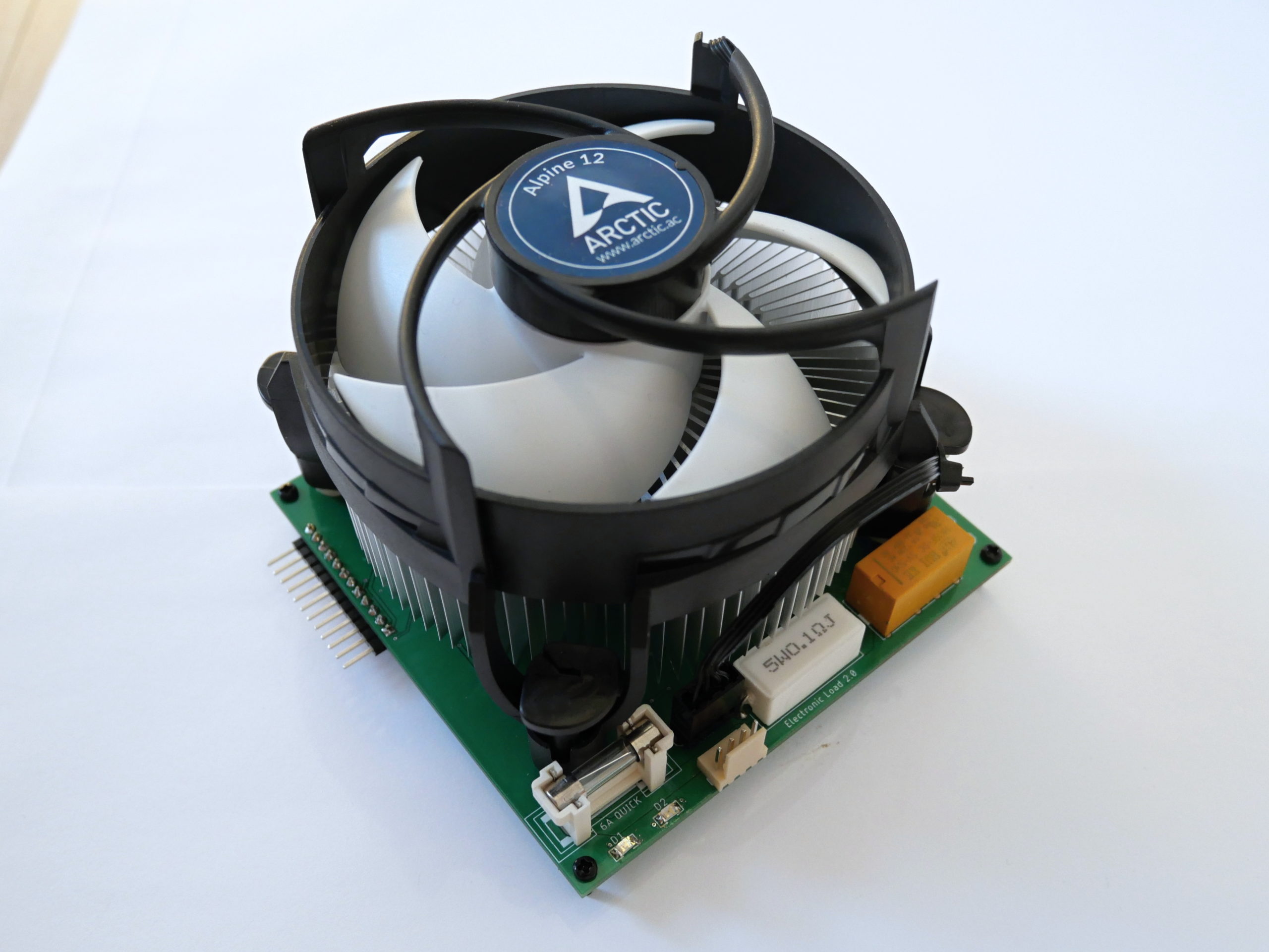
What probably caught your attention is the heatsink. I wanted this load to be able to dissipate up to 100 W of heat. Turns out, finding such a large heatsink is not easy and if you find one, they are expensive as hell. So I used an off-the-shelf CPU cooler – they are widely available, cheap (I got this one for under 10 USD!), come with a fan preattached and can dissipate a lot of heat – this one’s rated for 95 W.
The only challenge was mounting the TO-220 MOSFET, which is responsible for dissipating almost all of the heat, to the heatsink. You could probably somehow just press it against the heatsink, but I am not sure about the thermal resistivity and reliability of such a connection. So I drilled a hole in the heatsink and used a screw tap to make a screw thread in the soft aluminium. Afterwards, the MOSFET was simply screwed to the heatsink using an M3 screw, mica pad, isolation washer and some quality thermal paste.
Here are the features of the load module:
- up to 7 A CC load
- 2 voltage sense channels (selectable), max 27 or 50 V (depending on SW configuration)
- up to 100 W power dissipation
- UART/I2C control
- 0.1 % current and voltage measurement
- heatsink temperature measurement
- temperature controlled fan
- classical 5×20 fuse on the input
Now of course this load module needs to be paired with a display module (using UART or I2C) to make a fully standalone instrument. Below you can see the schematic for the load module, I am currently working on the display module and once it’s complete, I’ll put the entire project (schematic/PCB/firmware) on GitHub.

Conclusion
While this is still a work-in-progress, I am already really happy with the result. It can sustain the required 100 W continually and even more for a short period. There are some mistakes in this version, but none of them are critical, it’s mostly visual or just things I’d do differently next time, they are not necessarily wrong.
Hi Martin,
I dont find software and hardware file in your github. Can you send me link please?
Hi,
unfortunately, I paused the project because of lack of free time, so there are no files ready to be published…