Open Source Multimeter: development restarted
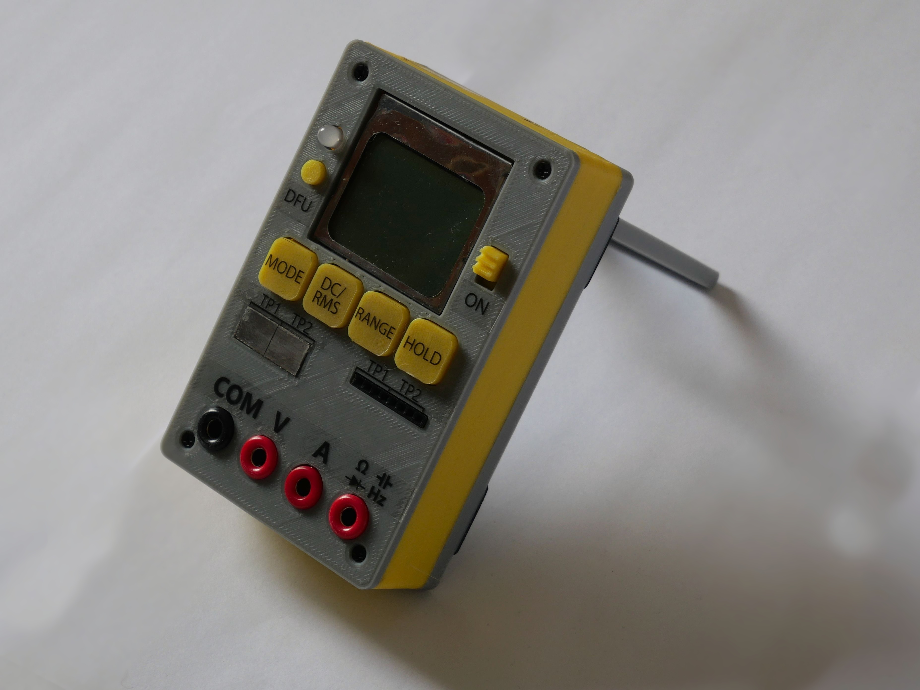
I’ve been using a couple of examples of my Open Source Multimeter revision 1.5 (you can see it above) for more than half a year now. I’ve been pretty satisfied with them – the software is stable, the accuracy hasn’t decreased much and since the meter is small, it doesn’t take much space on my desk, compared to some of the commercial ones I have.
That doesn’t, however, mean that there isn’t anything to improve. Probably the weakest point of rev 1.5 is the display. It uses the old Nokia 5110 LCD, which I thought was a good choice – it’s cheap and reasonably large (unlike some OLEDs, for example). But honestly, it’s too small for a multimeter, both physically and resulution-wise. The meter can capture a lot of data at a reasonable accuracy, but the problem is showing all of this data on such a small display. That also combines with the fact that there are only 4 buttons used to control all of the features of the meter, which really limits the amount of convenient functions you can implement.
And then there are other small things I’d like to improve – battery life could be extended, I wanter thermocouple input, expansion IO for automated measurement, the precision of the component testing circuitry could be increased, the current two-board layout isn’t very practical and so on.
But I was reluctant to restart the development, since I felt like the whole process is going to consume a lot of time and it won’t teach me anything new. But then I got in touch with Mr. Kent Swan (hkswan at gmail dot com), who offered to help with the development of the new revision. And given his superior experience with the whole research-development-manufacture process, I felt like this could really move this project up a few levels (and I could also learn a lot along the way).
And it indeed did. After counteless emails and tens of hours of research, here’s what we came up with:
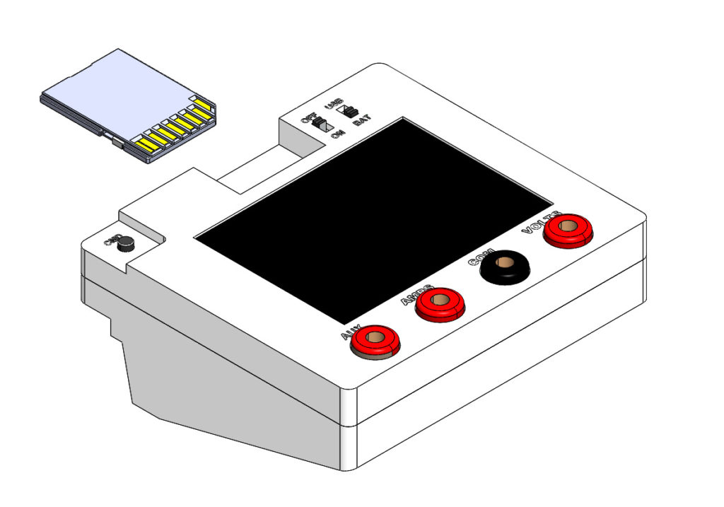
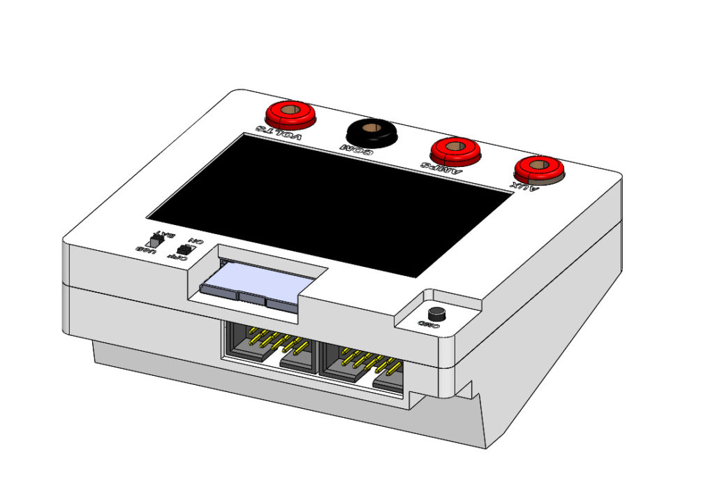
It contains a single PCB, which is around 80×70 mm (so still pretty cheap when you order it from China). The core of the system is still the same – STM32F373RC (so that’s the 64-pin version) coupled with a 2,8″ touch screen with an SD card like this one. There are still 4 bipolar ranges for voltage, 2 or 3 ranges for current (the current stage has been reworked and the testing will show how much is the 30 mA range usable), 5 ranges for capacity/resistance/inductance (again improved – it now uses the built-in comparator and DAC), diode testing, DAC waveform output, thermocouple input, EEPROM & SD-card slot, continuity testing, 2x 10-pin expansion ports (with I2C, SPI, UART), USB charging/isolation switch, space for an 18650 battery and probably lot of other things I forgot.
You’ve probably noticed that the case uses a strange “landscape” form-factor. At first, I wasn’t sure about this orientation, but the more I looked at it, the more I was starting to like it. And there are practical reasons, too – this formfactor allows the PCB to be under 100×100 mm, which is a costly limit to cross in most fabhouses. The angled part hides a space for an entire 18650 battery, which, combined with some power-saving circuitry, should give this beast a very long runtime. Also, I think that the slight angle is convenient – 99% of the time you are not looking at the multimeter exactly from top, so this improves both usability of the touchscreen and the readibility of the TFT.
The plan
Currently, we already have PCBs manufactured and on the way. So, if everything goes according to the plan, at some point in June we might release the source or at least some preliminary test results. And thanks to Kent’s hard work, this revision should come with a professional-grade BOM and PCB layout, and I’ll contribute to the effort by writing a full step-by-step build guide.
Stay tuned, because honestly, I have big expectations for this revision!
Looks really nice, I’d like to build it myself! How much is the total cost for parts for this?
Hi,
I haven’t calculated it yet, but it won’t be much more expensive than the previsous revision. So I’d say that you can squeeze the components below 15 or 20 USD. Without shippings, PCBs, 3D printing etc.
Hi, Martin! You wrote about improving components accuracy. Was it, particularly, about the choice to use 0.1% resistors ?
Hi,
well, it was a multitude of factors – the resistors, but also the input stage in general (ADC reference, tracing, …)
Why not use a STM32F405RGT6? This is a basic part in JLCPCBs stock so they won’t charge you assembly fee as they would for the STM32F373 which is an Extended part.
Because it doesn’t have the 373’s 16 bit SDADC the entire project is build around.
Gotcha, I’m a noob at programming stm32’s and I’m looking at your code and honestly i’m quite lost. I’m only used to the HAL API.
What toolchain do you use? Do you have a makefile to compile your code? Any good resources for programming bare metal like you do?
Hi,
I use Keil uVision, it’s project file is on GitHub. You can get Keil for free with a 32K limitation. Unfortunately, there isn’t a Makefile.
Regarding the bare metal approach – there isn’t anything I could recommend. I mostly work from datasheets and then experiment with the code…
You need to join the Embedded server on discord. I’ts very helpful
Lot of people with a lot of experience and knowledge https://discord.gg/muUs5w
Hey! Super excited to build one of these. When are you guys planning on releasing the docs?
Hi, well, since it’s a free time hobby project, it’s hard to give exact dates. My rough estimation is that we might have a working version by the end of June, but maybe not fully featured.
Do you have any progress updates?
Hi,
well, so far I was too busy with my commercial activities to work on this – hopefully I’ll have more time in August…
Would you like some help?
Well as of now, I think that would be counterintuitive, as I do not have any time for this project right now… So introducing more people into the project would just create more mess.
Well if you have the hardware done. I can get it manufactured and start programming in my free time i can just give you the code.
Would it be possible for you to share the hardware files? Gerbers and BOM? Any schematic/board files would be great too
Hello. Will component tester include ESR measurement? Although I suspect it won’t be too hard to implement with firmware update.
Honestly I do not plan on adding it now, but as you said, it should be just a firmware update.
I seem like a very nice project. Any updates? Maybe during the Christmas time?
Hi,
thanks for your interest. I’m afraid there won’t be any updates soon, as I’ve decided to skip to a next, fully reworked revision (with a 24 bit ADC and so)…
Hello, do you still want to use touch display and lithium-ion battery in 24-bit revision ? Are there any other interesting ideas you’ve came up with?
Still regularly checking this project’s page. Waiting for further updates =) Thanks.
Hello, do you still want to use touch display and lithium-ion battery in 24-bit revision ? Are there any other interesting ideas you’ve came up with?
Still regularly checking this project’s page. Waiting for further updates =) Thanks.
Hi,
I am sorry for stalling this, but my commercial activities are slowly taking all the time I’m willing to put into electronics. So it is still on my To-Do list, but TBH progress is really slow…
Hi! Are there any updates on project ?)
Hi..
I’m still waiting and always monitoring this project, is the development still ongoing?
Just pinging and letting you know that there are still people interested in this. 🙂
What is the status of this project?