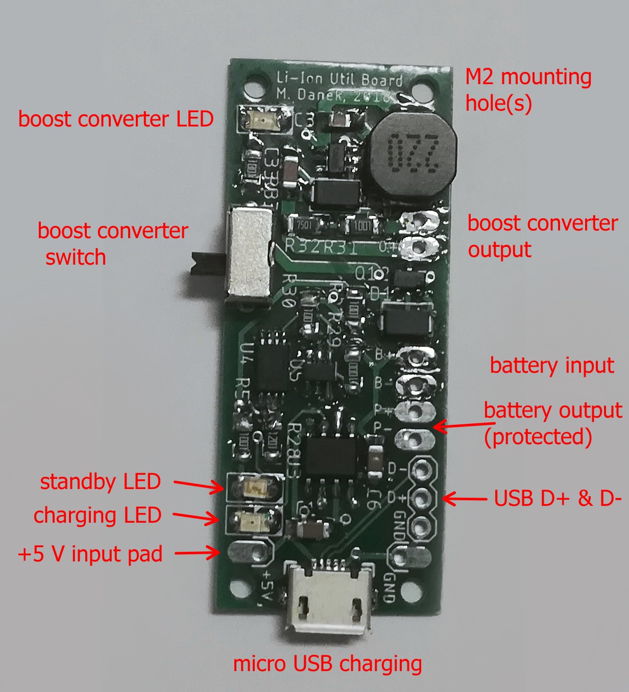
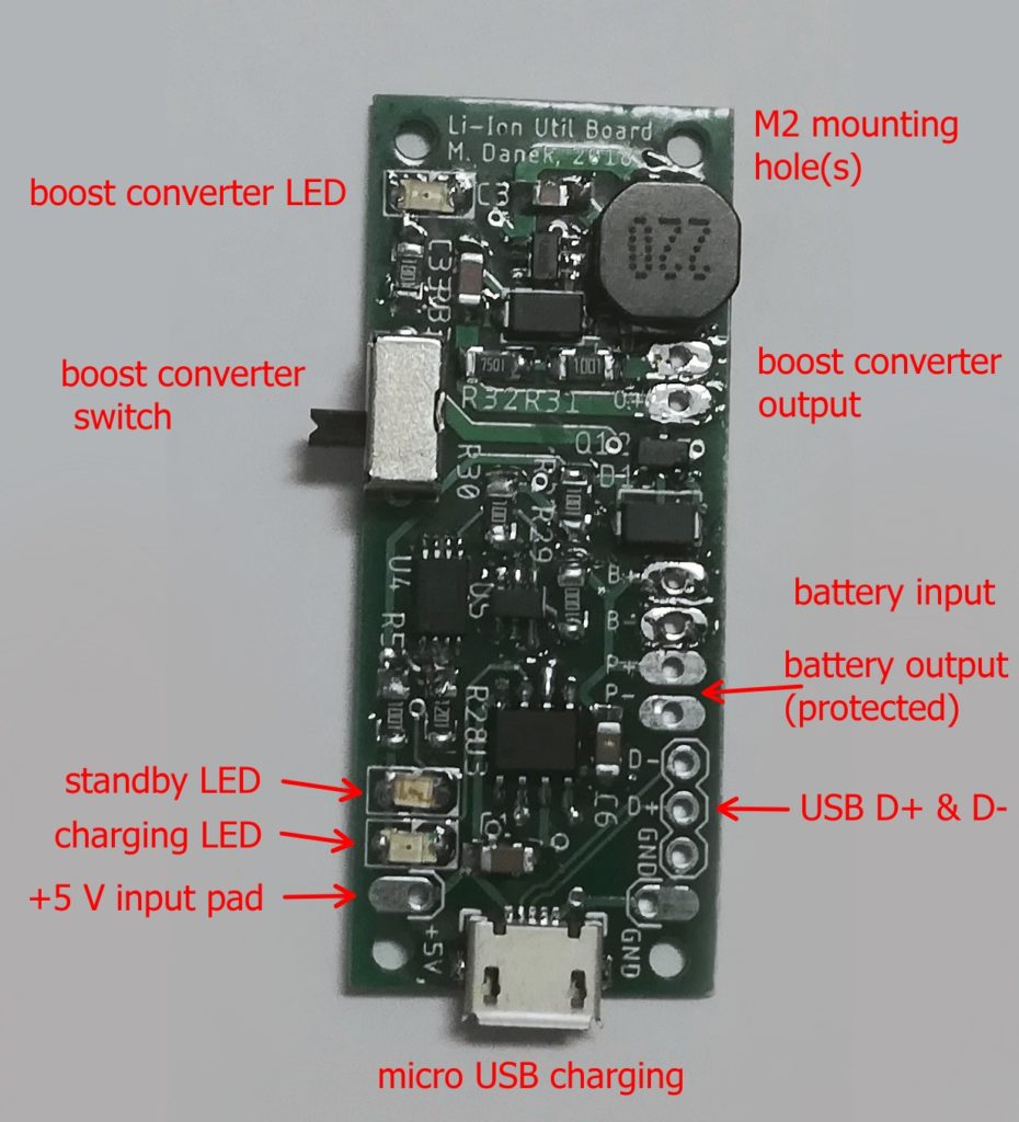
Lithium Battery Utility Board V1.2
I use lithium batteries a lot. However, they are not the easiest to use – you need a dedicated charging IC, complicated protection circuitry, boost module to power 5 V circuitry, switches, connectors… So I designed a board with all of these features.
This is hopefully the last and final revision of my Lithium Battery Utility Board (you can see the original post on Instructables here). It is relatively simple, but very useful board with the following features:
- charging circuit, capable of charging a lithium (Li-Ion or Li-Pol) battery with a current up to 1 amp; LED status indication
- battery protection circuit, protecting the battery from undervoltage, overvoltage, overcurrent and short-circuit
- load sharing circuit (you can charge and use the board at the same time, without screwing up the charging process)
- boost converter, which can boost the battery voltage anywhere from 4.8 to 28 volts; 1 amp output current at 5 V output
Specs
| Recommended | Absolute | |
| USB/+5V pad input voltage [V] | 4.0 – 5.5 | -0.3 – 8 |
| max charging current [mA] | 1000 | 1200 |
| trickle charge current [mA] | 130 | — |
| battery undervoltage protection [V] | 2.4/2.9 | — |
| battery overvoltage protection [V] | 4.25 | — |
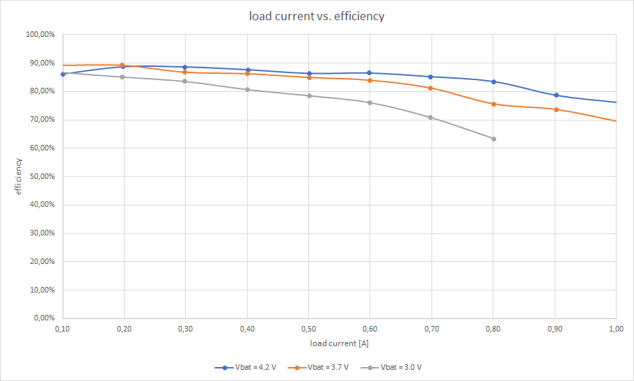
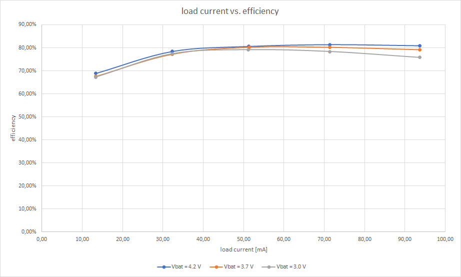
| efficiency (circa) [%] | 70 – 90 | — |
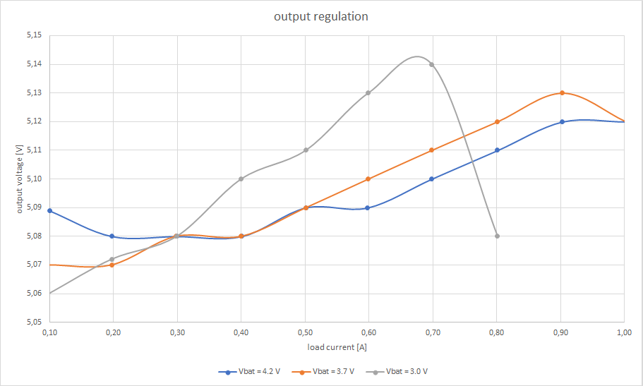
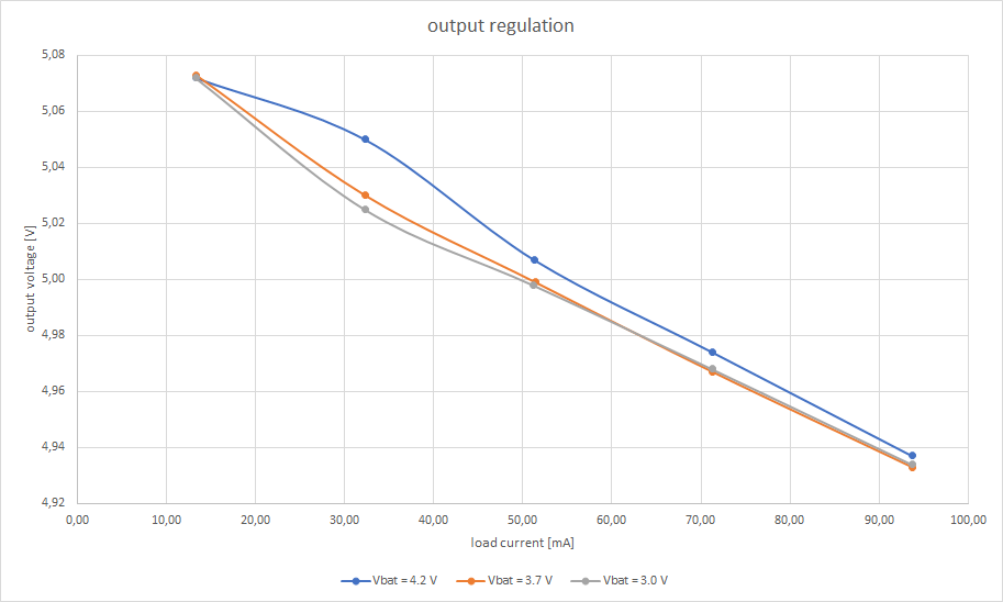
| output regulation | see below |
Input and charging circuit
As an input connector, I chose micro USB – it is very popular and you can use a jellybean phone charger to supply +5 V (however, it must be capable of supplying the required current – 1 amp for charging and 1 amp for the output!). I also included two pads, +5 V and GND, so you can solder wires to these directly, if you want. And also I routed out the D+ and D- pins from the USB connector, so if you for example want to provide power and also use the same USB to transfer data, you can solder to these pads. Just keep in mind that the D+ and D- are differential, so you need to keep wire lengths the same (and ideally use a shielded, twisted pair for longer cables).
The charging is realized using the very popular TP4056, which offers CC-CV charging with trickle charge. The battery is charged to 4.2 V with a user-adjustable current up to 1 amp. The charging current is determined by R3 according to the formula I = 1200 / R3. The datasheet states absolute maximum for charging current as 1.2 amps.
The TP4056 provides two open-drain outputs for status LEDs. These are routed out in such a way that you can either solder in a 1206 SMD LED, legs of a normal 5 mm LED, which can then be bent sideways, or cables, which can then be connected to a microcontroller (then you need to set up your micros pins as inputs with pullups). And lastly, there is a thermal pad beneath the TP4056 – do not forget to put some thermal grease before you solder in the IC.
Protection and load sharing
The protection itself is realized using two ICs – the first one is a dual MOSFET, I used the 8205A, which uses TSSOP8 package (if you are ordering these, do not mistake them with the 8205S, which are SOT23-6 package). The seconds IC is the protection controller – you can either use the DW01, which is more common, but the overdischarge voltage is 2.4 V, which I think is too low for me. Therefore I prefer to use the FS312, which is exactly the same, just the overdischarge voltage is set to 2.9 V, which is more suitable for the average lithium battery.
Note – calculating the overcurrent/short circuit current: the protection IC uses both MOSFETs in series as a sense resistor. And since their resistance can vary quite a bit, it is impossible to determine the exact trip current. But according to my calculations, with DW01 and 8205A it is around 2.5 A.
Note – starting the protection circuitry: when you first connect a battery, you need to “enable” the protection circuitry by plugging in the USB charging for just a brief moment (literally half a second will do).
The load balancing circuitry is also very important – it would be impossible to charge the battery and use the connected device at the same time (since the charging process depends on measuring battery current, if you tried drawing current from the battery at the same time, you might get it stuck in a CC loop and damage the battery). So the load balancing circuitry makes a low resistance automatic switch, which will basically power the boost converter from the +5 V source instead of the battery when it is present. So the + 5 V input will be divided between the battery charging IC and the boost converter section. If you are interested to see how the load sharing part works, see my GitHub, there is a folder with a few pictures as an explanation.
Boost converter
I used the MT3608 boost IC, since I had good experience with it before. In this revision, I highly optimized the layout of all the switching components, so the efficiency is usually close to 80 % (see below), which is pretty good for something this simple and cheap. My goal was to achieve 800 mA output across the whole Li-Ion battery voltage range (e. g. 3.0 – 4.2 V), and I did succeed. And with voltages above circa 3.3 V, it can even output stable 1 amp. In fact it can output 1 amp across the whole Li-Ion battery voltage range, but the protection circuitry will kick in and prevent you from drawing more than 2.5 amps from the battery.
note: with no load, the board draws about 5 mA (half of that is the boost converter LED)
Additional sources
When I published the previous article about this, I got quite a few people ask me if I am willing to sell these boards. Since I ordered V1.2 boards and parts in large numbers, I am willing to sell a few of these – assembled and tested or just parts, depends on you. Here’s a link.
- Eagle drawings (schematics and PCB) and partlist on GitHub
- original Instructables article
- EEVBlog – charging lithium batteries

hello, nice project! it’s been a 6 years, but maybe you still answering.
(https://embedblog.eu/?p=91) I have a question on V12. There is no protection on the boost converter circut, right? So if a shortcut on the BC output will occure board will be damaged. I am working on my first project in electronics and want to use your circut diagram as an example for my power supply system