An interesting experiment: cooling a Cree LED on a normal FR4 PCB
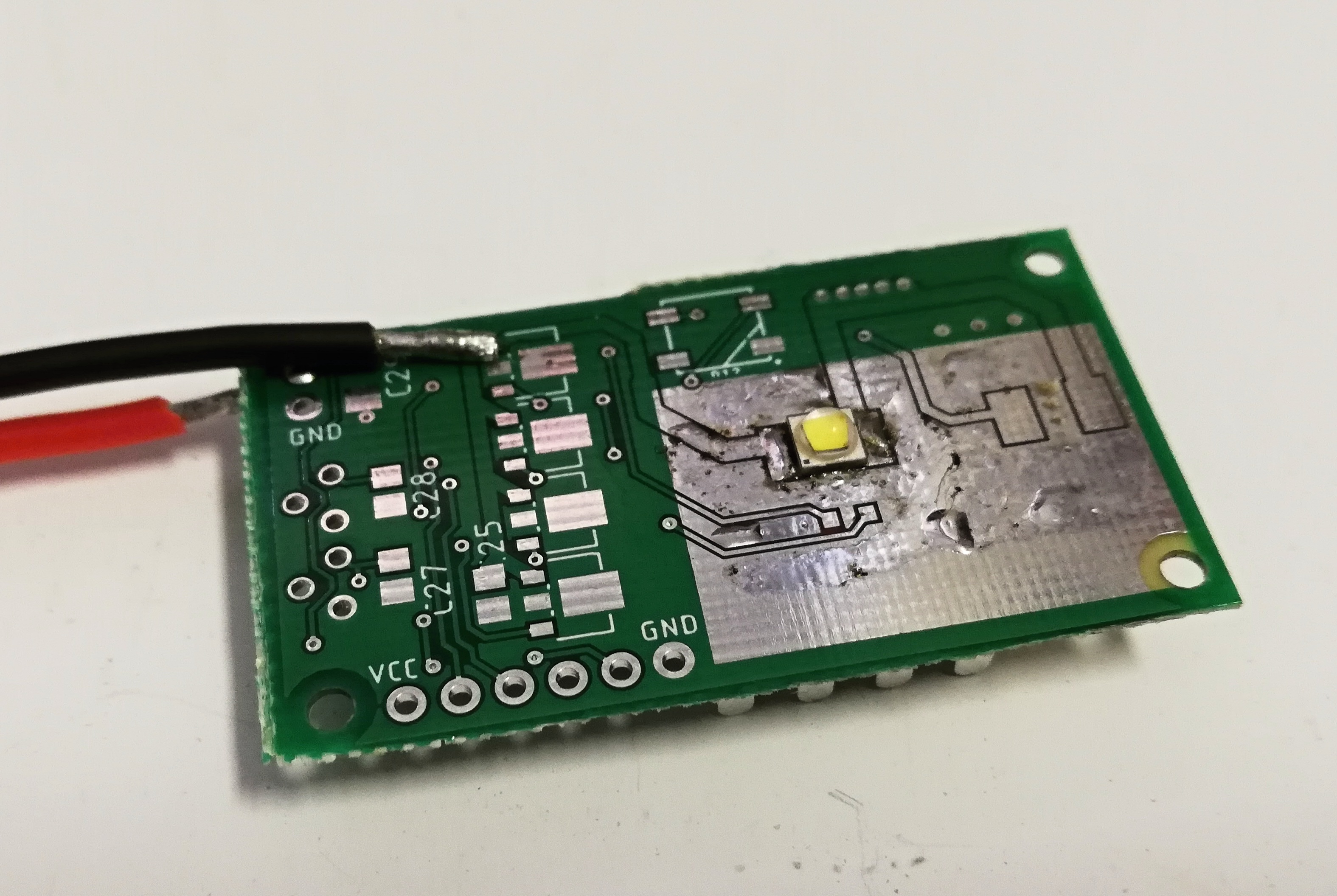
Modern LEDs have enormous efficiency – up to 40 % – but this still means that if you mount a 5 W LED on a PCB it will generate up to 3.5 W of heat. In one of my recent experiments, I tried making a headlamp using a Cree XPG-BWT LED. I made a small PCB for this purpose, with this LED and some driving circuitry (ATtiny24, CC sinks, and an RGB diode – because why not).
Normally, you would use aluminium-core board, which would spread and dissipate the heat well. But I wanted to see whenever it is possible to mount a 4.65 W LED on a normal FR4 board (the core of FR4 is glass-reinforced epoxy laminate, which is not particularly thermally conductive). For this reason, I ordered relatively thin board (0.8 mm) and made large areas of bare copper around the diode. On the front side (the side with the diode), there were 400 mm2 of bare copper and another 550 mm2 were on the bottom side. Both sides were interconnected with a lot of vias, with the intention that I will glue a small heatsink on the bottom side of the board with thermally conductive glue.
I reflowed the LED to the board and tinned all of the bare copper around the diode. I also filled all vias with solder to improve their thermal conductivity. Then I attached a thermocouple to the base of the diode and started driving the LED with constant current while carefully watching the temperature. However, without the heatsink I was not capable of driving the LED even with 700 mA. Here are the results:
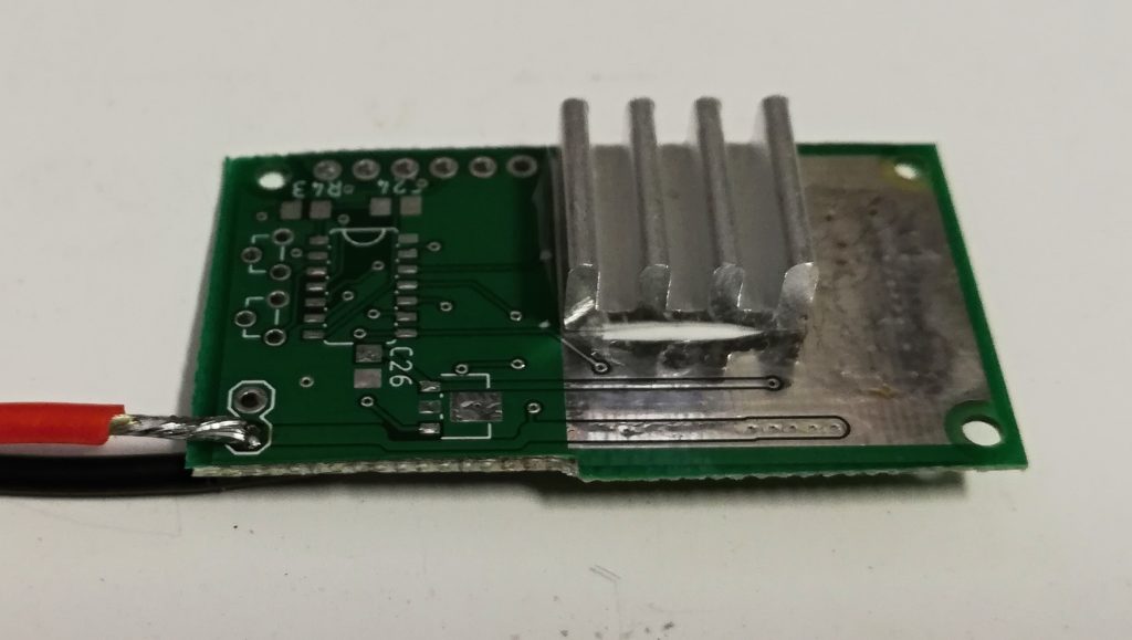
So I used thermally conductive glue and attached a small 14 * 14 * 6 mm heatsink. This – not surprisingly – improved the cooling a little bit with the following results:
| Current [mA] | Power [W] | Temperature [°C] |
| 350 | 1 | 37 |
| 700 | 2 | 65 |
| 1050 | 3 | 91 |
Note: the ambient temperature was 18 °C and there was no artificial airflow around the board.
Conclusion
Even a large area of bare copper (‘PCB heatsink’) cannot dissipate more than a few watts of heat. However, it can conduct the heat OK – at 1 amp, the LED was at 91 °C while the heatsink was at 78 °C. So the problem is more in the actual dissipation, not in conducting the heat away from the LED.
Note on driving the LEDs: the redneck way is to just put a resistor between the LED and the power source, but you probably know that a constant current is a much better idea. I recently discovered a very handy IC – the AMC7135, which is a 350-mA CC sink. It is widely available from many Chinese sites.
Could you please contact me on what’sapp
+97474760006
Hi,
sorry, I’m not gonna call some unknown number. If you want, feel free to send me an email (see the ‘About’ page)
Hello,
Nice work! However, I think the test was compromised because you solder tinned all the bare copper. The thermal conductivity of solder is around 50-60 W*m-1*K-1 which is 7 times less than that of pure copper which is around 350-360 W*m-1*K-1.
Hi,
you are is certainly correct, though there was some solder already from HASL and my intention was to mostly fill the vias to improve their thermal conductivity…
Hello again,
I am not completely sure if filling the vias with solder would actually speed up the heat transfer process. While it definitely increases the contact area, as the solder has significantly lower heat conductivity it might lead to hot points in the vias and poorer heat dissipation (I guess). I am really interested in seeing the results with bare copper areas.
I am currently working on automotive light bulbs with SMD LED-s and I really want to design them to have proper cooling (already made one prototype to test). And I am wandering if I can use FR4 boards or should I search for aluminium core ones.
Have a nice day!