Testing the range of NRF24L01+ modules
One of the biggest trends these days is making everything wireless. And sometimes it really comes in handy to have a radio module capable of transmitting data between two microcontrollers. And because I don’t know that much about radios, I have to stick to ready-made modules, like the NRF24L01. While you can get a lot of theoretical information from the datasheet, you have to test one practical and very important specification – the range. Since there is a lot of conflicting information on the internet, I decided to perform my own tests to determine the real life range, and here I bring the results.
Testing conditions
There is a very nice video by GreatScott on YouTube, where he compares the range of some readily-available radio modules, including the NRF24L01. However, I think that some of the things he did in the video were not done correctly. When working with (basically any) radio module, you should:
- Avoid powering the module from switch-mode power supplies, in order to provide the module with as little noise as possible (he used a powerbank, which contains a switch mode boost converter and it is super noisy at the output)
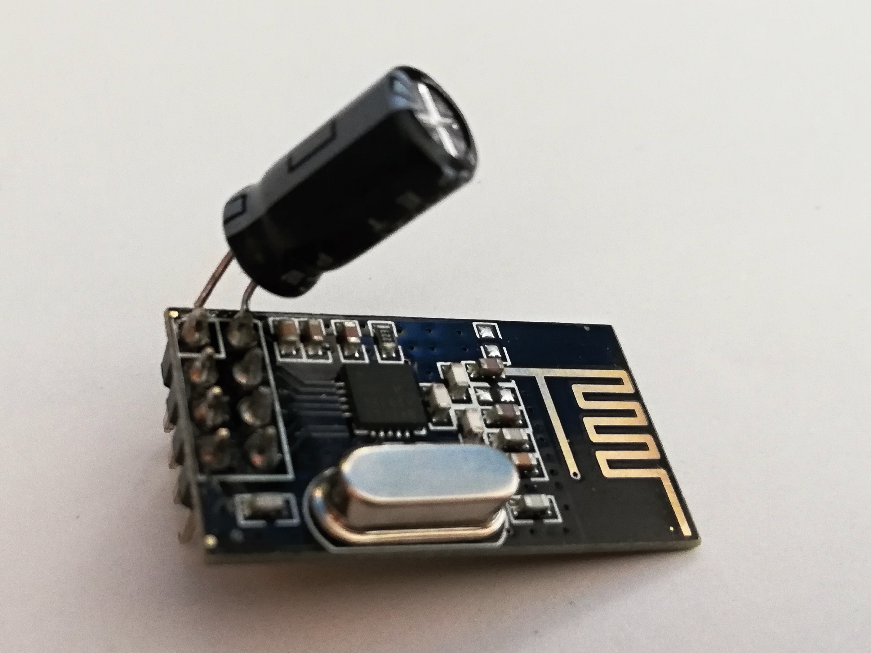
- decouple the module with a capacitor as close to the IC as possible (see photos below)
To improve the range with the NRF24L01 in particular, you can also:
- use a high channel number, this way you will operate outside of the 2.4 GHz WiFi/bluetooth band
- choose a lower bitrate (I used the lowest – 250 kbps)
- shield the powered module (see below)
Test rig
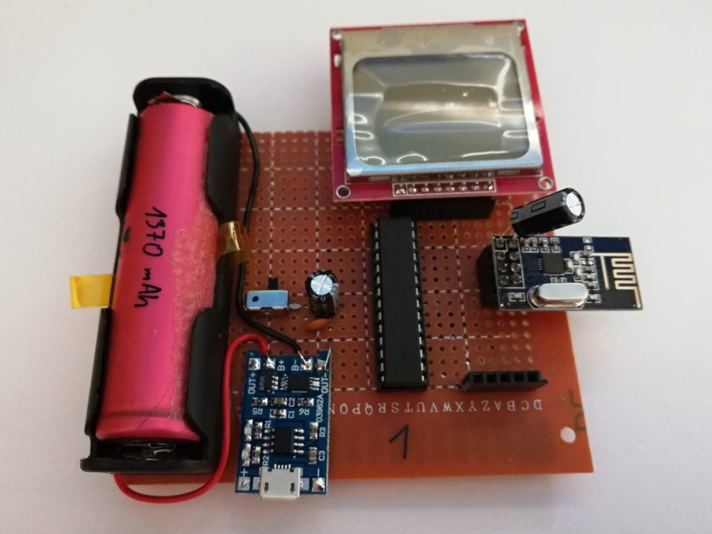
Based on the requirements above, I made two simple test rigs using an ATmega 328, some 18650 cells, a display and a linear 3V regulator. There is really nothing special about those, I just took extra care to put enough capacitors on the power rails to provide the radio module with smooth input voltage. In all tests, I had one rig as a receiver and one as a transmitter, with both containing a radio module of the same type (ie both having the amplified version or both having the normal version).
Normal module
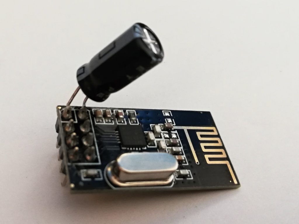
This is the “classical” module – it contains only the NRF chip and a small PCB antenna. Those modules are super cheap (1 USD/pc on Ebay), but they rely solely on the power of the integrated amplifier inside the NRF chip, so their range is limited. The only hardware change I did to these modules before testing them was that I soldered a 100 μF capacitor between the VCC and GND pins.
When testing inside a house, I was capable of getting 100 % packet reception at the distance of 12 meters at the same floor. But that is with a lot of walls in between the receiver and transmitter and also multiple WiFi networks present, which is a challenging environment for every radio module operating at this frequency. On different floors, I was getting about 80 % packet reception, which is to be expected – there is the thick steel-concrete ceiling in between the receiver and transmitter.
In open terrain I got much better results. With a clear line of sight, I was capable of getting 100 % reception at the distance of 47 m. After that, it started to be very unreliable, and the signal eventually died totally at about 70 metres. However, it is worth mentioning that this was still done on a normal city street, that is with a lot of interference and metal objects nearby. Also because of the design of the antenna, the reception was very dependent on the orientation of the module.
PA + LNA module
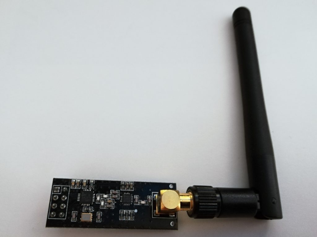
This module is slightly more expensive at about 2,5 dollars per piece, but it contains a Power Amplifier, Low Noise Amplifier and an external antenna. There is, however, no shielding present, which is why I wrapped it in clear masking tape, then aluminium foil and them wrapped a wire around that, which is connected to ground. Crude, sure, but it should reduce interference.
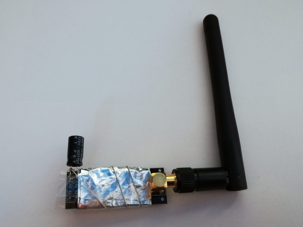
In a house, the results were OK – there were no blind spots and I was getting good reception even on different floors.
The real disappointment came when I was testing the module outside. I was outdoors, with almost zero interference and a clear line of sight, but even so I was getting reliable reception at only roughly 480 metres. This time, it did not depend on the orientation of the antenna, but if I broke the line of sight (by, for example, just standing between the receiver and transmitter), it immediately stopped receiving.
Conclusion
Generally, I was disappointed, mostly by the PA+LNA module. Some users on the internet claim ranges up to 1 km, but I was not capable of repeating such results. Maybe a longer antenna would increase the range, or buying a more expensive module might help.
Hello
How can I test the packet data reception?
Is there any command to check this and to check if the transmitter is well connected/transmitting?
I thank you for your availability
Best Regards,
Rafael Freitas
HEY . I NEED TO ASK. I MADE A CIRCUIT USING NRF24 WITH EXTERNAL ANTENNA NEED A RANGE ABIUT 6O/7O METERS BUT ITS NOT WORKING. I AM CONFUSED THAT ALL PINS OF ANTENNAS ARE WITH GROUNF. THERS N +VE PIN
Can you repeat the test at lower bands? As the frequency increases, line of sight becomes more and more important.
I received a few of these amplified modules. However, I could not figure out the pinout. Can you help?
Hello, I’ve tried range of those modules on a pair: normal 24L01+ with PCB antenna, the same as you have in the picture on top of the page. And second was “power amplified” version to which I connected ISM16 antenna http://www.csatshop.sk/product/ism16-39/ with sieve (reflector) dimension 310x430mm and it woreked bidirectionally 250kbps with no packet loss on 4km! Only one module was power amplified+LNA, the second was only the 24L01 chip.