Brymen BM867/869 interface cable
Recently I was looking for a good and precise digital multimeter to buy, and the Brymen 867, a 50000-counts handheld DMM, immediately caught my eye. It even had the PC interface I wanted, since I want to use it for some automated measurements. So after a bit of research, I finally decided to buy it for about 165 €. I then searched for the PC interface cable, and …. whoa, the cable costs another 50 €?! Well, I am not paying that for a stupid cable, especially when it contains just a simple IR transceiver and an USB converter.
Note: there is an updated version of this interface cable, see here.

As with any other DIY project, the first (and very important step) is to do some research. Obviously I am not the first one to face this problem, so what have others discovered about the protocol?
- there is an entire thread about making this adapter on the EEVBlog forum
- also on the same forum, the user Sairus made an alternative software
- and Brymen released a short PDF about the protocol
So people have made these adapters before, and they have obviously sniffed out the protocol. Great, less work for me! The protocol is not complicated, but it is completely human-unreadable. Most cables just take the raw data, retransmit it to the computer and then you need to use a dedicated software to translate it into normal, readable, numbers. Or this is at least how Brymen and most people on the forum did it. I, on the other hand, decided that I will decode the protocol inside the microprocessor driving the cable, and then I will send readable text over UART to the PC.

the whole data transmission
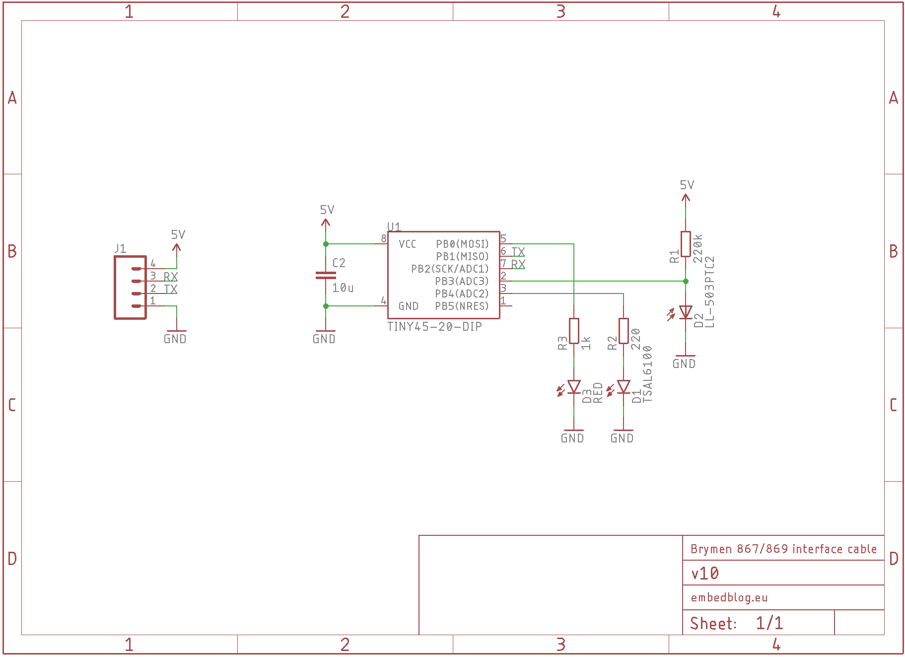
As the core of my project I used an ATtiny25 with 2 kB of flash and 128 B of SRAM. To communicate with the DMM, I chose the TSAL6100 (940 nm 10° IR LED) and to receive data I chose the LL-503PTC2 (940 nm 30° IR phototransistor). Then I started developing the firmware, which was not hard, since from link #2 I got a PDF with a lot of information. Just two things in this PDF are either wrong or missing – first, the data are sent LSB first, even though it looks like the opposite at a first glance. And also, do not read data on the first rising clock, it is probably some sort of “synchronization clock”.

Now we have a simple routine which gets the data. Most of the cables would now dump all the available data to the computer, but, as I said before, I wanted the ATtiny to translate the data and send only readable text. So I tried to program this routine… and I managed to fit the firmware onto the IC, it just takes 97 % of the flash memory and 98 % of the SRAM. That’s what I call a tight fit!
But it works just fine, which is what matters. Also, I implemented a simple control protocol, which you can use to control the rate at which it sends data. Just send the appropriate command over UART to the device:
- 0xC1 to transmit data at max rate (usually about 5 times a second)
- 0xC2 to transmit data once per second
- 0xC3 to stop sending data
- 0xC4 to send a single reading (when stopped)

So the last step was the hardware. I did not want to bother making a PCB, so I just soldered everything on a piece of perfboard and made a simple case, which I 3D printed out of PLA. You may need to tweak the size a little bit, so it makes a tight fit inside the Brymen’s connector. Once everything was done, I screwed it together and filled it with silicon, to make it at least a little bit splash proof. Here’s the schematics and how it looked open and then finished:


So, what’s the conclusion? Well, it was totally worth it. The total cost with ATtiny25 and also an USB-UART cable was around 3 €, it took me 6 hours of development and prototyping and 2 hours assembling the thing, and now I have a working cable. Feel free to build your own, all the files are on my GitHub.