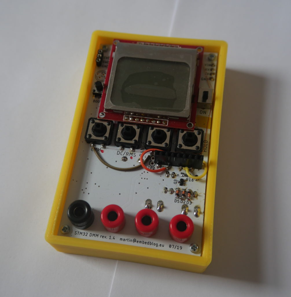
STM32 Open Source multimeter – revision 1.4
I was hoping that this release of my multimeter project will be the final one. However, during testing, I still discovered things that needed changing or modifying, so in this article, I’ll at least describe some of the biggest changes and achievements of this revision & and also what went wrong and forced me to make yet another revision. In September, parts and PCBs for rev 1.5 should arrive and I’ll try to populate, test and publish it ASAP.
Change #1 – new microcontroller
As mentioned previously, I changed the microcontroller to an STM32F373CCT6, which is from the high precision line of ST’s microcontrollers, targeted at mixed-signal processing. The main reason for this change was the ADC – or better said, the ADCs. There are three 16-bit Σ-Δ ADCs with differential input, dedicated reference pin and also PGA (programmable gain amplifiers). So we should should be getting much better results than the ADC on the old ’32F103, right?
Well, yes and no. Yes, they are more accurate and have all that fancy stuff I described above. But they totally require calibration of both offset and gain – out-of-the-box, they are terrible. Even though ST provides an auto-calibration feature, it A) calibrates only offset and B) is totally inaccurate (at least I have not managed to make it accurate). So what you need to do is make a simple two point calibration – you compare the raw ADC values at 95 % of the max positive and negative range against a known voltage source. I then made an Excel spreadsheet, into which you input those numbers and it outputs two constants. After this calibration, the results mostly fit into 0,1 % accuracy margin. Another handy thing is that this calibration calibrates not only the ADC, but the whole AFE (analog front end) – so it even compensates for resistor inaccuracy etc.
The only downside is that we need to store those two calibration values somewhere – one option is to compile the program with them, but this is stupid for obvious reasons. So I had to put a small 2 kB EEPROM on the board. Thankfully, these cheap EEPROMs cost just a few cents each.
Accuracy
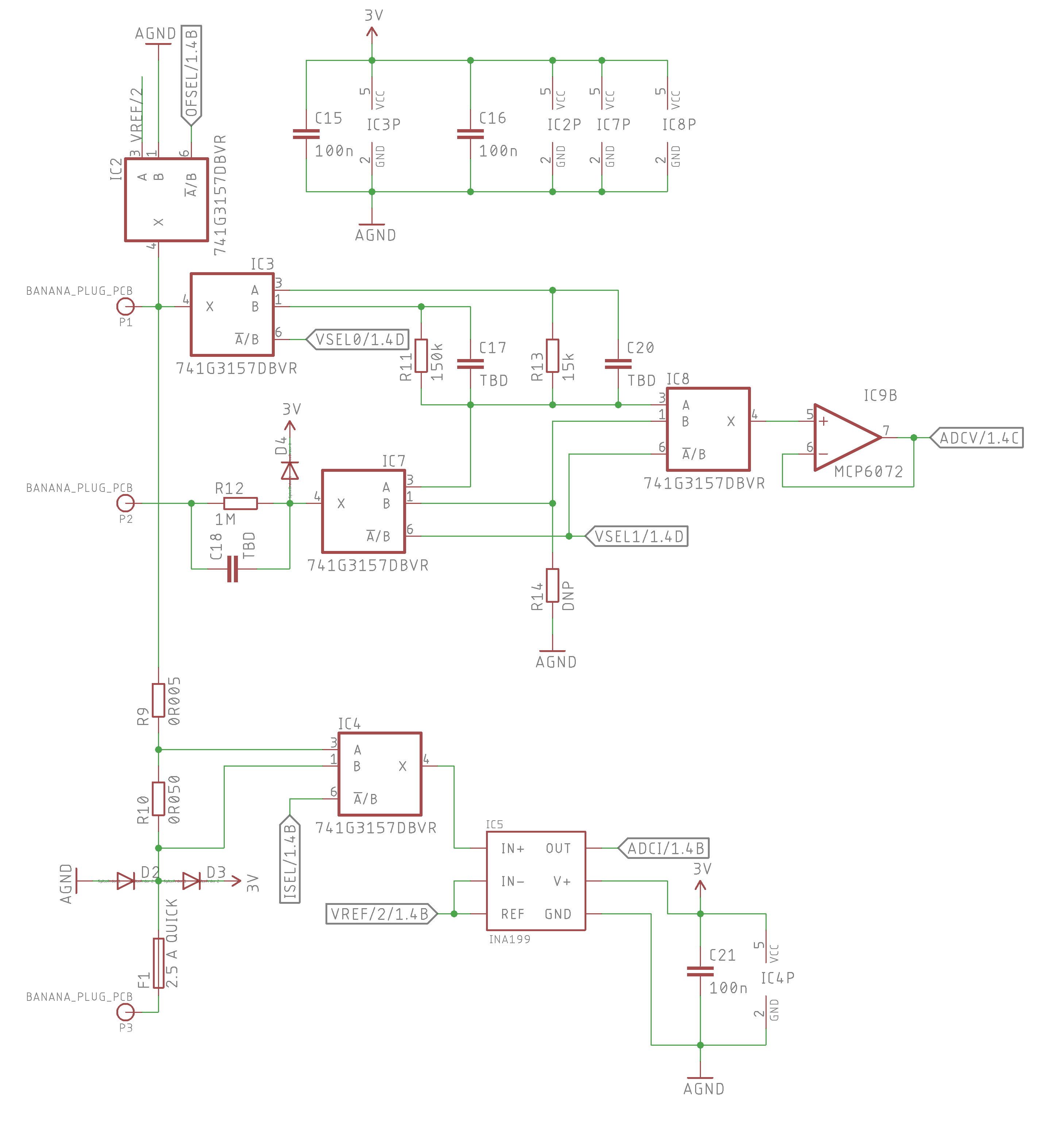
Just to remind you, this is how the AFE looks:

And this is how it fared for the ±6 V range (this is after calibration, and the reference line is 0.1 % tolerance):
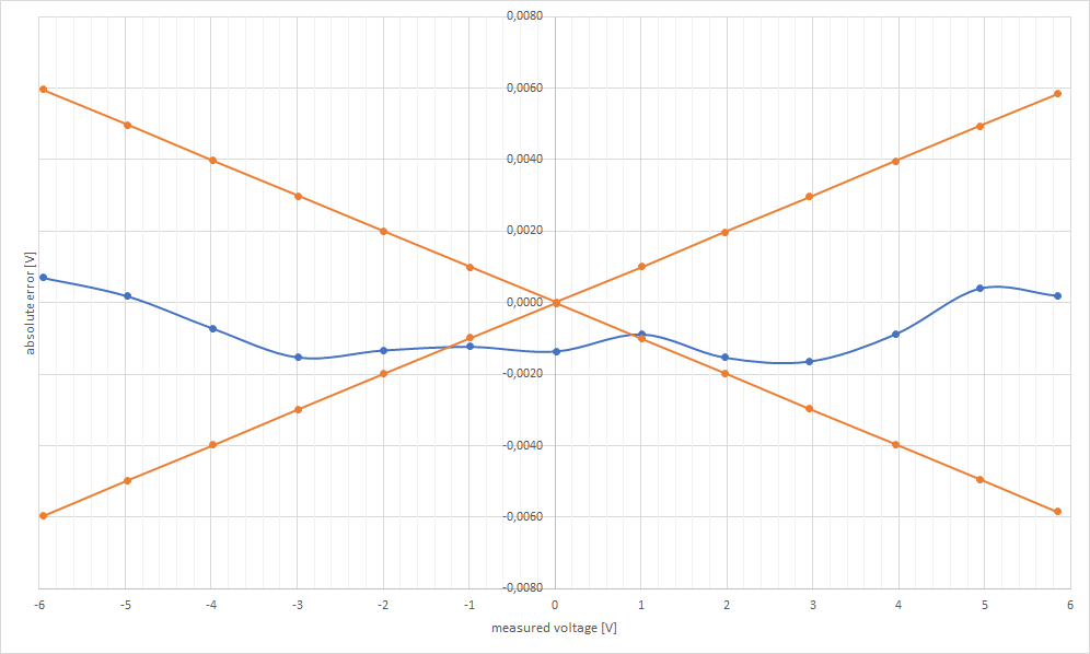
As I already mentioned in my project log on Hackaday, in this range the largest error we got was 1.6 mV.
Now what about the two milivolt ranges? Well, in 1.3, we had problems with offset of the 100x gain amplifier. So I tried to use an auto-zero opamp ( the MCP6V81) hoping to get rid of the offset multiplied by 100. I got rid of this offset, but the output was so noisy that it was almost unusable. I had no choice but to design yet another analog front end to fulfill my 0,1 % goal. Here’s what I came up with:
Basically, instead of dividing and then multiplying the value, now the AFE enables a “direct input” mode, where the input voltage goes directly into the ADC (thru a voltage follower opamp, of course). This makes the ±600 mV range simple, since the ADC has a max voltage of ±900 mV. So it is, in fact, a ±900 mV range.
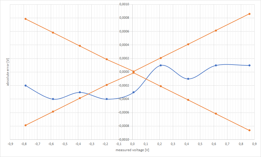
The ±60 mV range is also relatively straight forward – we just use the integrated PGA with a gain of 8 or 16. As far as real results go, here’s the ±900 mV range:
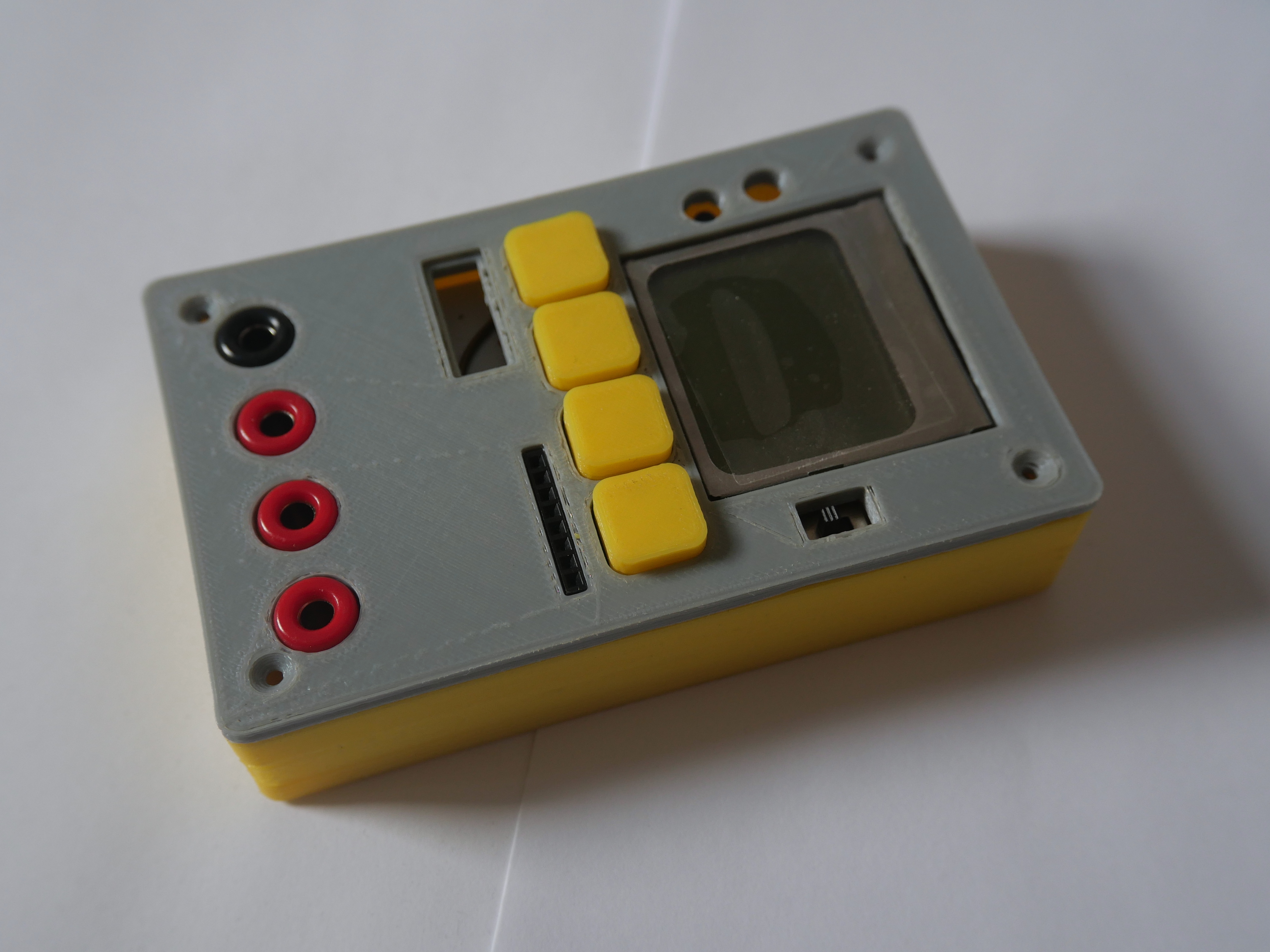
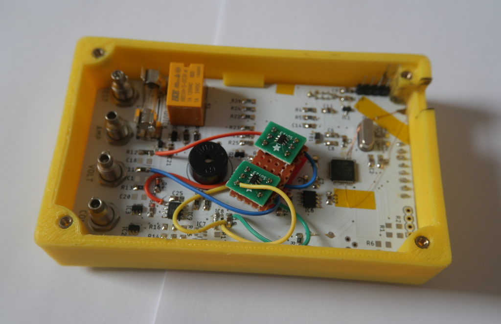
Change #2: Better layout
This time I thought about the enclosure before drawing the PCB, and I think it paid off – it looks much better than the previous versions! The PCB itself is slightly larger (60 x 100 mm) and also the case now uses 3 mm thick 3D-printed walls, so the result is slightly larger in area, but it is thinner and much much sturdier. I’ll just need a way to put labels on the 3D printed parts.
Change #3: Test points
I reduced the the number of Test Points from three to two, but now both of them have 3 different resistances connected, which allows more precise measurement of capacity, resistance, diode drop etc. Also it now supports measuring frequency (this is not yet implemented in software, but will be) and also the DAC’s output is connected here – maybe we will find a use for this in the future.
Change #4: Firmware
Of course some parts of the software needed a total rework, because we are using a different processor – but generally the software side still need some work, I want to implement frequency measurement, improve the UART connection and also the component test.
Conclusion
I did not publish this revision to GitHub – simply because there were too many mistakes on the PCBs. But as I said in the begining, I am really hoping that 1.5 will be the final revision and I’ll have time to finish a smooth out the firmware.
nice project, thanks for it! I’ll make it to use it with oscilloscope gfxscope 3.0 and urlc meter
Please can you tel me where can I find the technical information regarding design of PCB for voltages current and resistance. Please share files related to that if you can.
Hi, everything is available on my GitHUb.
Nice job! I want to make a same one. But could you tell me how to calibrate when I finish building?
Thanks!
Hi,
basically, you’ll need a tool to calibrate it against (as accurate as possible) and a powersupply. Then just measure a value of roughly 10% and 90% of each range with both tools and input it into the Excel chart available on GitHub (the folder with calibration firmware). This will calculate you gain and offset for each range. Copy these values from Excel into the calibration firmware, compile and upload it into the multimeter. This will save them into EEPROM. Then just upload the regular firmware and you are done – it takes about 15 minutes, once you figure it out.
That will be very helpful. Thank you very much!